Dosage accurate control-type anesthesia outfit
A controlled and precise technology, applied in the field of anesthesia, can solve the problem of precise dose control that cannot be easily controlled, and achieve the effect of convenient operation and lightening of the burden.
- Summary
- Abstract
- Description
- Claims
- Application Information
AI Technical Summary
Problems solved by technology
Method used
Image

Examples
Embodiment 2
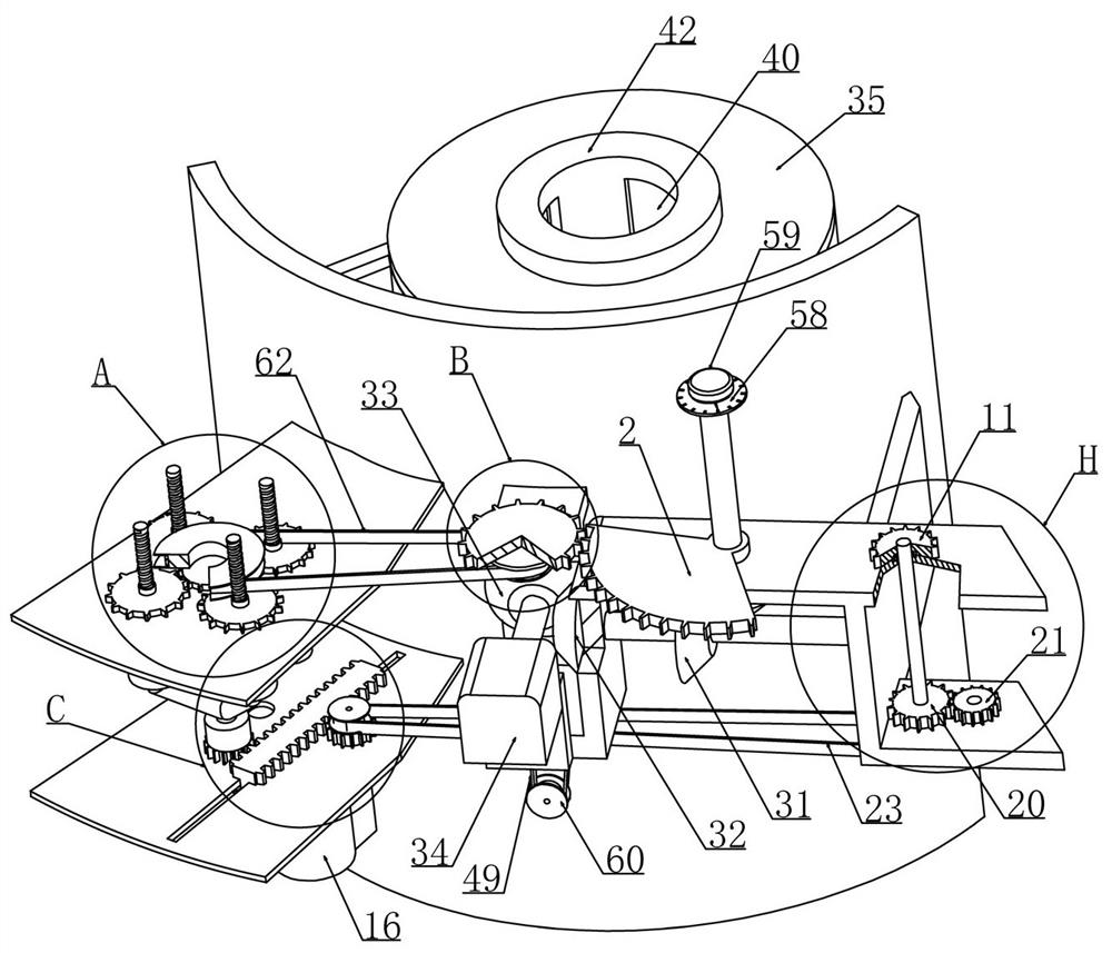
[0055] Embodiment 2, on the basis of Embodiment 1, the first gear transmission includes a fifth gear 20 coaxially rotatable with the fourth gear 11 and mounted on the case 1, and the fifth gear 20 is meshed with a rotatably mounted on the case The sixth gear 21 on the body 1, the sixth gear 21 is coaxially rotated with a first pulley 22 and the first pulley 22 cooperates with the first belt 23, and the other end of the first belt 23 is equipped with a rotation The second pulley 24 on the box body 1 and the second pulley 24 is coaxially rotatably installed with a seventh gear 25 meshing with the double-sided rack 9 .
[0056] When this embodiment is in use, refer to the attached figure 2 As shown, we rotate the fourth gear 11 on the box body 1 and also coaxially rotate the fifth gear 20 at the lower end of the fourth gear 11. The sixth gear 21, the radius of the sixth tooth 21 is smaller than that of the fifth gear 20, referring to the attached Figure 11 As shown, we instal...
Embodiment 3
[0058] Embodiment 3, on the basis of Embodiment 1, the medicament mixing device includes a cylinder 26 fixedly connected with several medicament cartridges 7 and a circular ring 27 is rotatably installed inside the cylinder 26, and the outer circular surface of the circular ring 27 surrounds The first tooth system 28 is provided and the first tooth system 28 is meshed with the double-sided rack 9. A number of fan blades 74 are fixedly installed in the circular ring 27 coaxially. The lower end of the circular ring 27 is rotatably fitted with a The conduit 29 on the box body 1 and the other end of the conduit 29 is connected to the extruding cylinder 16 , and the first fan-shaped plate 14 can realize the connection or disconnection between the control ring 27 and the conduit 29 .
[0059] When this embodiment is in use, refer to the attached Figure 24 As shown, the medicament mixing device includes a cylinder 26 and the cylinder 26 is a double-layer annular structure. The cross...
Embodiment 4
[0060] Embodiment 4, on the basis of Embodiment 1, a first one-way bevel gear 30 coaxially arranged with the sector gear 2 is rotatably installed on the box body 1, and the first one-way bevel gear 30 and the sector gear 2 The first one-way bevel gear 30 meshes with the second bevel gear 31 which is rotatably mounted on the box body 1 and the second bevel gear 31 is coaxially rotatably mounted with a third bevel gear 32. The three bevel gears 32 mesh with a fourth bevel gear 33 rotatably mounted on the casing 1 and the fourth bevel gear 33 is driven by a motor 34 .
[0061] When this embodiment is in use, refer to the attached Figure 7 As shown, the first one-way bevel gear 30 is installed with the coaxial rotation at the lower end of the sector gear 2. In order to prevent the first one-way bevel gear 30 from rotating with the sector gear 2 when the anesthetic dose is adjusted, that is, turning the handle 59, thereby driving other The rotation of the device causes the initia...
PUM
 Abstract
Description
Claims
Application Information
 - Generate Ideas
- Intellectual Property
- Life Sciences
- Materials
- Tech Scout
- Unparalleled Data Quality
- Higher Quality Content
- 60% Fewer Hallucinations
Browse by: Latest US Patents, China's latest patents, Technical Efficacy Thesaurus, Application Domain, Technology Topic, Popular Technical Reports.
© 2025 PatSnap. All rights reserved.Legal|Privacy policy|Modern Slavery Act Transparency Statement|Sitemap|About US| Contact US: help@patsnap.com