Supercharge Your Innovation With Domain-Expert AI Agents!

Automatic grinding robot for spiral welds at pipe end of spiral steel pipe

A technology of spiral welds and spiral steel pipes, which is applied in the direction of grinding racks, grinding machine parts, grinding machines, etc., can solve the problems of unsatisfactory weld bead quality at the end of spiral steel pipes, and achieve high power utilization of machine tools, maintenance Smooth grinding surface and high productivity

Active Publication Date: 2020-10-16
宝鸡宇喆工业科技有限公司
View PDF4 Cites 0 Cited by
  • Summary
  • Abstract
  • Description
  • Claims
  • Application Information

AI Technical Summary

Problems solved by technology

[0006] The technical problem solved by the present invention is to provide an automatic grinding robot for the spiral weld seam at the end of a spiral steel pipe. A two-degree-of-freedom fine-grinding actuator is installed at the execution end of the multi-degree-of-freedom manipulator. On the one hand, it can simplify the motion control of the manipulator, and at the same time improve Grinding accuracy of the manipulator execution end; overcoming the quality of the weld bead at the end of the spiral steel pipe after grinding by the multi-degree-of-freedom grinding manipulator in the prior art cannot meet the process index requirements stipulated in the API Spec5L standard and the GBT97111-1997 standard; manual secondary grinding is still required technical challenge

Method used


Image

  • Automatic grinding robot for spiral welds at pipe end of spiral steel pipe
  • Automatic grinding robot for spiral welds at pipe end of spiral steel pipe
  • Automatic grinding robot for spiral welds at pipe end of spiral steel pipe

Examples


Embodiment Construction

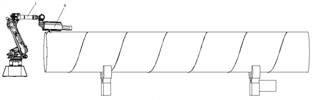
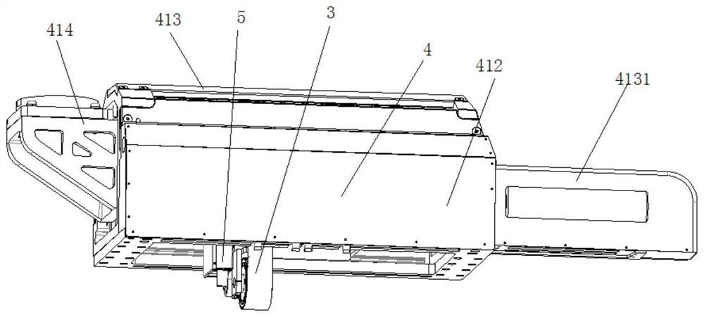
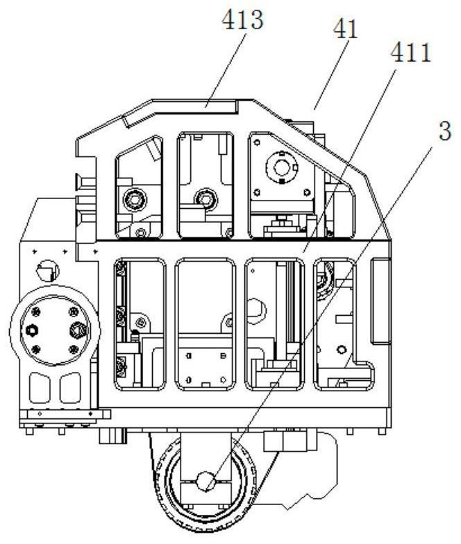
[0063] Attached below Figure 1-35 Specific examples of the present invention are described. It should be understood that the embodiments described below are only illustrative rather than specific limitations on the present invention.

[0064] The following examples facilitate a better understanding of the present invention, but do not limit the present invention. The experimental methods in the following examples are conventional methods unless otherwise specified. The components and materials used in the following examples are commercially available unless otherwise specified. The implementation of the control circuit in the following embodiments is a conventional control method unless otherwise specified.

[0065] In the present invention, unless stated otherwise, it should be understood that the terms "center", "upper", "lower", "front", "rear", "left", "right", "vertical The orientations or positional relationships indicated by "straight", "horizontal", "top", "bottom...


PUM


Abstract

The invention provides an automatic grinding robot for spiral welds at the pipe end of a spiral steel pipe. A two-degree-of-freedom accurate grinding executing mechanism provided with a laser profilometer is arranged at the executing end of a multi-degree-of-freedom manipulator, so that the grinding precision of the manipulator is improved while motion control is simplified, and the problem that manual secondary grinding is still needed due to the fact that the quality of a weld bead at the pipe end of the spiral steel pipe ground by a multi-degree-of-freedom grinding manipulator cannot meet the process index requirements specified by the API Spec5L standard and the GBT97111-1997 standard in the prior art is solved. The automatic grinding robot for the spiral welds at the pipe end of the spiral steel pipe not only can be used for grinding outer welds of the spiral steel pipe, but also is suitable for grinding inner welds of the spiral steel pipe, and a base metal is not damaged duringgrinding; the minimum residual height after grinding can be smaller than or equal to 0.1 mm and is far higher than the requirements of API Spec5L standard and GBT9711-1997 standard; and the laser profilometer cooperates with a special detection algorithm, and high-precision scanning detection with the precision smaller than 0.05 mm can be achieved, so that powerful technical support is provided for high-precision weld grinding.

Description

technical field [0001] The invention belongs to the technical field of operation, transportation, grinding and polishing, and in particular relates to an automatic grinding robot for spiral weld seams at pipe ends of spiral steel pipes. Background technique [0002] Spiral steel pipe is a pipe made of strip steel coil as raw material and rolled by spiral welding process. For the spiral steel pipe, in order to meet the welding quality of the next step of the steel pipe butt girth welding of the spiral steel pipe end, the API Spec5L standard and the GBT97111-1997 standard both clearly stipulate: Take the weld seam of the spiral steel pipe end with a diameter of 508mm as an example: First, The weld reinforcement within the range of at least 150mm from the pipe end of the spiral welded pipe should be removed, that is, the length of the axial grinding depth of the spiral steel pipe end is required; secondly, the weld bead after grinding should not be lower than the pipe body pare...

Claims


Application Information

Patent Timeline
IPC IPC(8): B24B21/02B24B21/00B24B21/18B24B21/20B24B49/12B24B27/00B24B41/02B25J11/00
CPCB24B21/02B24B21/002B24B21/18B24B21/20B24B49/12B24B27/0084B24B41/02B25J11/0065
Inventor 原小红张瑾宇朱雅光尹志远马利王林军
Owner 宝鸡宇喆工业科技有限公司
Features
  • R&D
  • Intellectual Property
  • Life Sciences
  • Materials
  • Tech Scout
  • Unparalleled Data Quality
  • Higher Quality Content
  • 60% Fewer Hallucinations
Learn More