Hydraulic magneto-rheological composite brake structure for vehicle

A magneto-rheological and brake technology, which is applied in the direction of liquid resistance brakes, brakes, brake components, etc., can solve the problems of insufficient braking force of hydraulic magnetic fluid brakes, and achieve the effect of easy installation and fixation

Pending Publication Date: 2020-10-16
YANCHENG TONGJI AUTO PARTS CO LTD
View PDF0 Cites 2 Cited by
  • Summary
  • Abstract
  • Description
  • Claims
  • Application Information

AI Technical Summary

Problems solved by technology

[0004] The purpose of the present invention is to provide a vehicle hydraulic magneto-rheological composite brake structure to solve the problem that the existing hydraulic magneto-rheological brakes proposed in the background technology are mostly made smaller in size in order to reduce their own size. There is a problem of insufficient braking force of the hydraulic magnetic current brake, and a large current is required to pass through the coil to make the coil generate a large magnetic force, thereby obtaining sufficient braking force.

Method used


Image

  • Hydraulic magneto-rheological composite brake structure for vehicle

Examples


Embodiment

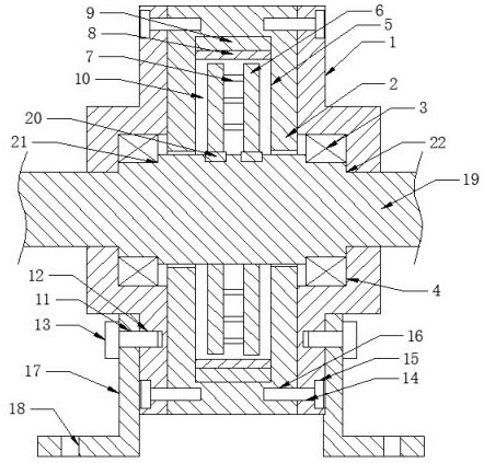
[0022] see figure 1 , the present invention provides a technical solution: a vehicle hydraulic magneto-rheological composite brake structure, including a housing 1, the middle part of the housing 1 is provided with a hole for the main shaft 19 to pass through, the number of the housing 1 is two, The positions of the two housings 1 correspond to the left and right, and the middle part of the housing 1 is provided with a bearing hole 4, and a bearing 3 is installed in the bearing hole 4, and a main shaft 19 is installed between the bearings 3 on the left and right sides, The middle part of the main shaft 19 is equipped with a brake shell 2, and the brake shell 2 is located between the shells 1 on the left and right sides. The cross sections of the shell 1 and the brake shell 2 are circular, and the shell 1 and the brake shell The maximum outer diameter of the shell 2 is equal, the outer edge of the housing 1 is provided with a countersunk hole 15, the outer edge of the brake hou...


PUM


Abstract

The invention belongs to the technical field of magneto-rheological brakes, and especially relates to a hydraulic magneto-rheological composite brake structure for a vehicle. The composite brake structure comprises shells, and the number of the shells is two. The positions of the two shells correspond to each other left and right; a bearing hole is formed in the middle of each shell; a bearing ismounted in each bearing hole; a main shaft is mounted between the bearings on the left side and the right side; a brake shell is mounted in the middle of the main shaft; and the brake shell is locatedbetween the shells on the left side and the right side, counter bores are formed in the outer edges of the shells, first threaded holes are formed in the outer edge of the brake shell, the counter bores correspond to the first threaded holes in position in a left-right mode, and a first bolt is placed in each counter bore. Current passes through a coil to enable the coil to generate magnetic force, and magneto-rheological fluid generates large resisting moment under the action of a strong magnetic field to hinder movement of a brake disc, so the main shaft is braked; and due to the arrangement of the brake blades, the brake disc bears large resistance in the braking process, and enough braking force is achieved.

Description

technical field [0001] The invention relates to the technical field of magnetorheological brakes, in particular to a hydraulic magnetorheological composite brake structure for vehicles. Background technique [0002] Magneto-rheological fluid, referred to as MR fluid, is a controllable fluid and is a relatively active research in smart materials. Magnetorheological fluid is a suspension formed by mixing tiny soft magnetic particles with high magnetic permeability and low magnetic hysteresis and non-magnetic liquid. This suspension exhibits low-viscosity Newtonian fluid properties under zero magnetic field conditions; and high-viscosity, low-fluidity properties under the action of a strong magnetic field. Using the precisely adjustable shear stress of the magneto-rheological fluid, the magnetorheological fluid is applied to the automobile braking system, and the braking torque of the brake is adjusted by controlling the current of the magnetic field circuit, which is a hydrau...

Claims


Application Information

Patent Timeline
Patent Type & Authority Applications(China)
IPC IPC(8): B60T8/17B60T1/087F16D57/00
CPCB60T1/087B60T8/17F16D57/00
Inventor 章志尧
Owner YANCHENG TONGJI AUTO PARTS CO LTD
Why Eureka
Try Eureka