Radio frequency transmission device for spiral wave plasma electric thruster

A plasma and electric thruster technology, applied in the field of radio frequency transmission devices, can solve problems such as electromagnetic interference parasitic plasma, and achieve the effects of improving efficiency and stability, suppressing the generation of parasitic plasma, and eliminating characteristic impedance

Inactive Publication Date: 2020-10-16
BEIJING INST OF SPACECRAFT ENVIRONMENT ENG
View PDF4 Cites 2 Cited by
  • Summary
  • Abstract
  • Description
  • Claims
  • Application Information

AI Technical Summary

Problems solved by technology

[0004] The purpose of the present invention is: in order to solve the traditional radio frequency transmission device for helical wave plasma electric propulsion, it is difficult to transmit the power output by the radio frequency power supply to the discharge antenna without damage, and at the same time, the overflow of electromagnetic interference and the problem of parasitic plasma will be generated, and A proposed RF transmission device for helicon wave plasma electric propulsion

Method used


Image

  • Radio frequency transmission device for spiral wave plasma electric thruster
  • Radio frequency transmission device for spiral wave plasma electric thruster
  • Radio frequency transmission device for spiral wave plasma electric thruster

Examples


Embodiment 1

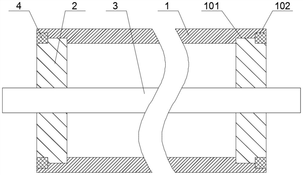
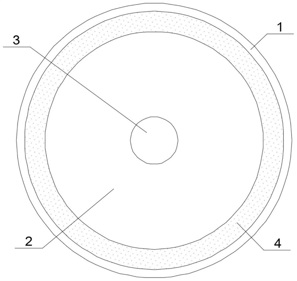
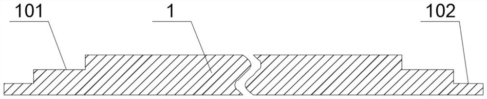
[0028] See Figure 1-5 , The present invention provides a technical solution: a radio frequency transmission device for a spiral wave plasma electric thruster, comprising a rigid metal tubular outer conductor 1, a cylindrical insulating block 2, a metal rod-shaped central conductor 3 and a metal washer 4. The inner wall of the metal tubular outer conductor 1 is successively provided with a first step 101 and a second step 102 from the middle to both ends. The two ends of the rigid metal tubular outer conductor 1 are located on the inner wall of the first step 101, and cylindrical insulating blocks 2 are embedded in the inner wall The outer end of the cylindrical insulating block 2 is provided with a stepped groove 201, and the outer end of the cylindrical insulating block 2 is located between the second step 102 and the stepped groove 201, and a metal washer 4 is sleeved. The axis of the rigid metal tubular outer conductor 1 A metal rod-shaped central conductor 3 penetrating the...

Embodiment 2

[0030] Specific, such as Figure 1-4 As shown, the inner diameter of the first step 101 is equal to the outer diameter of the cylindrical insulating block 2, the inner diameter of the second step 102 is equal to the outer diameter of the metal washer 4, and the inner diameter of the metal washer 4 is equal to the outer diameter of the step groove 201, this structure The arrangement improves the stability of the combined assembly between the rigid metal tubular outer conductor 1, the cylindrical insulating block 2 and the metal gasket 4. The cylindrical insulating block 2 is provided with a central through hole 202 at the center of the circle, and the central through hole 202 is connected to The metal rod-shaped center conductor 3 is in a transitional fit. The selection of the transitional fit method improves the stability of the fit between the cylindrical insulating block 2 and the remaining metal rod-shaped center conductors 3.

Embodiment 3

[0032] Specific, such as Figure 1-4 As shown, the material of the rigid metal tubular outer conductor 1, the metal rod-shaped central conductor 3, and the metal gasket 4 is preferably copper, but not limited to copper. The selection of this material improves the rigid metal tubular outer conductor 1, the metal rod-shaped central conductor 3. In addition to the transmission performance of the metal gasket 4, the material of the cylindrical insulating block 2 is preferably polytetrafluoroethylene, but not limited to polytetrafluoroethylene. The selection of this material improves the insulating performance and corrosion resistance of the cylindrical insulating block 2 Performance and high temperature resistance.

[0033] Working principle: During manufacturing, the metal rod-shaped central conductor 3 is inserted through the rigid metal tubular outer conductor 1, and the metal rod-shaped central conductor 3 is bracketed at the axis of the rigid metal tubular outer conductor 1, and...


PUM


Abstract

The invention discloses a radio frequency transmission device for a spiral wave plasma electric thruster. The radio frequency transmission device comprises a rigid metal tubular outer conductor, cylindrical insulating blocks, a metal rod-shaped central conductor and a metal gasket, the inner walls of the two ends of the rigid metal tubular outer conductor are sequentially provided with a first step and a second step from the middle to the two ends. The cylindrical insulating blocks are embedded in the portions, located on the inner wall of the first step, of the two ends of the rigid metal tubular outer conductor, stepped grooves are formed in the outer ends of the cylindrical insulating blocks, and the portions, located between the second step and the stepped grooves, of the outer ends ofthe cylindrical insulating blocks are sleeved with the metal gasket. According to the invention, a combined bracket type transmission structure is adopted, the power output by the radio frequency power supply can be transmitted to the discharge antenna in a lossless manner, and meanwhile, the phenomena of overflow of electromagnetic interference and parasitic plasmas in the transmission process are avoided, so that the high efficiency and stability of radio frequency transmission are improved.

Description

Technical field [0001] The invention relates to the technical field of space electric propulsion, and in particular to a radio frequency transmission device for a spiral wave plasma electric thruster. Background technique [0002] The spiral wave plasma electric thruster has the characteristics of long electrodeless discharge life, high thrust, large specific impulse, light weight, and low plume electrical neutrality to the spacecraft body potential. It is very suitable for orbital maneuvering, orbital maintenance of high-orbit satellites. Deep space exploration has a long life. The spiral wave electric thruster uses the radio frequency power generated by the radio frequency power supply and applies it to the discharge antenna to excite the plasma to accelerate the generation of thrust. [0003] Compared with the radio frequency power supply, the spiral wave electric thruster is a fluctuating low impedance load. The radio frequency coaxial cable cannot transmit the power output by...

Claims


Application Information

Patent Timeline
Patent Type & Authority Applications(China)
IPC IPC(8): H04B1/38F03H1/00
CPCH04B1/38
Inventor 彭毓川赵华丁亮郑慧奇任琼英李涛姜利祥唐振宇焦子龙孙继鹏
Owner BEIJING INST OF SPACECRAFT ENVIRONMENT ENG
Why Eureka
Try Eureka