Spacecraft vertical recovery landing system, spacecraft and recovery landing method

A landing system and spacecraft technology, applied in the aerospace field, can solve problems such as complex landing gear system, aircraft aerodynamic shape and structural thermal protection design, which have great influence and technical difficulty

Active Publication Date: 2020-10-20
北京凌空天行科技有限责任公司
View PDF0 Cites 5 Cited by
  • Summary
  • Abstract
  • Description
  • Claims
  • Application Information

AI Technical Summary

Problems solved by technology

However, this method is generally applicable to winged aircraft, and has a complex landing gear system compared to parachute landing, which has a greater impact on the aerodynamic shape and structural thermal protection design of the aircraft. It is technically difficult, and the proportion of inert mass is large, which affects the carrying capacity. It is also relatively large. In addition, it has strict requirements on the landing site and requires a dedicated airport runway.

Method used


Image

  • Spacecraft vertical recovery landing system, spacecraft and recovery landing method
  • Spacecraft vertical recovery landing system, spacecraft and recovery landing method
  • Spacecraft vertical recovery landing system, spacecraft and recovery landing method

Examples


Embodiment 1

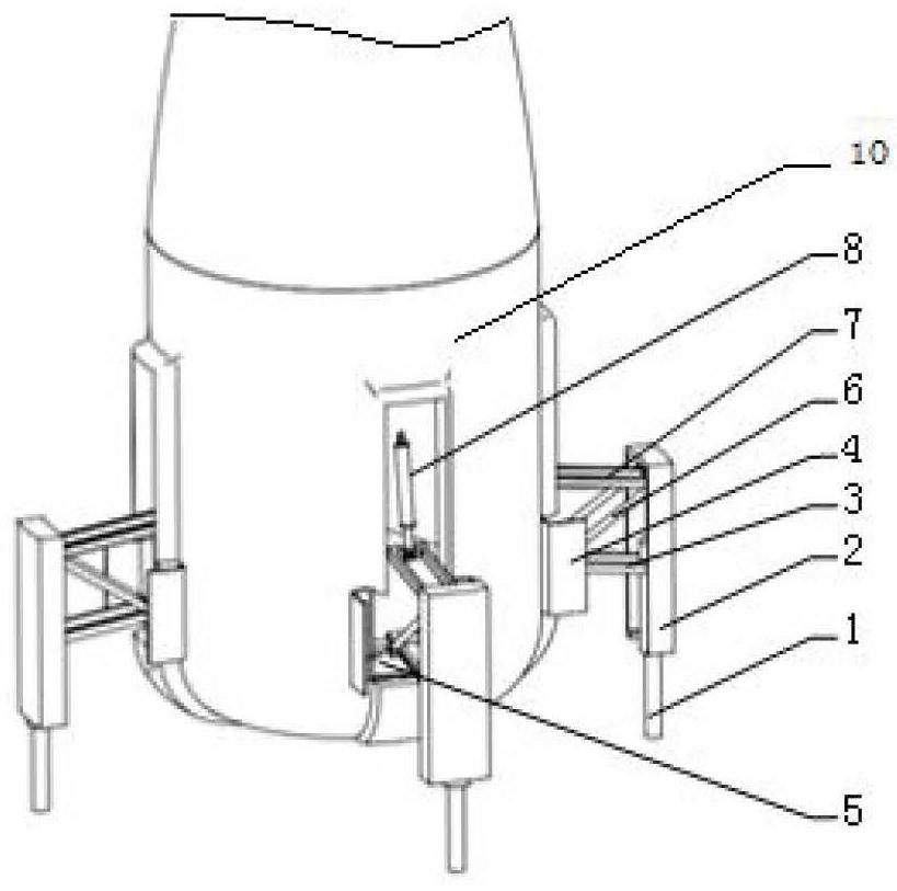
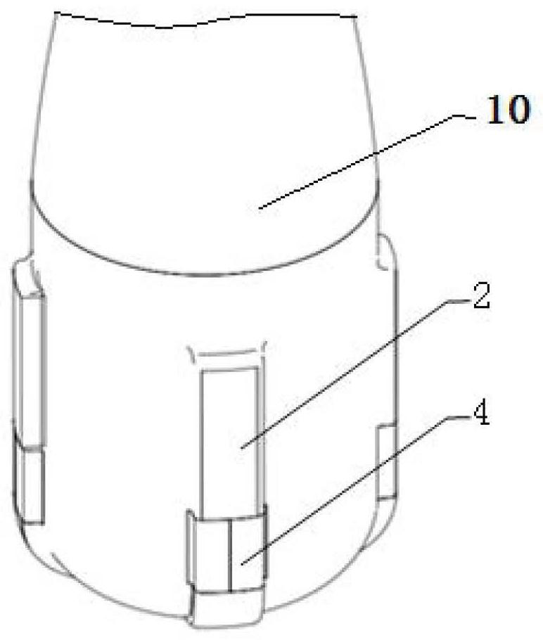
[0043] like Figure 1 to Figure 4 As shown, this embodiment provides a spacecraft vertical recovery landing system, including a thrust reverser 9 arranged at the bottom of the spacecraft, for providing a braking force opposite to the landing direction when the spacecraft 10 lands, so as to realize spaceflight The landing deceleration of the spacecraft 10; also includes 4 groups of landing buffer devices evenly arranged on the bottom side of the spacecraft 10.

[0044] Each set of landing buffer devices includes a buffer outer cylinder 2, a buffer piston rod 1, a strut slide rail 3, a hatch 4, a hatch pull rod 5, a strut 6, a rocker arm 7 and an actuator 8;

[0045] The buffer outer cylinder 2 is fixed on the bottom side wall of the spacecraft 10 through a pyrotechnic separation device; the buffer outer cylinder 2 is opened to form a groove on the side facing the spacecraft 10; the buffer piston rod 1 Installed in the middle and lower part of the groove, and protruding from th...

Embodiment 2

[0066] This embodiment provides a spacecraft equipped with the landing system described in Embodiment 1, and the spacecraft is any one of a vehicle, a return capsule, a lunar lander or a planetary lander.

Embodiment 3

[0068] like Figure 10 As shown, this embodiment provides a landing method based on the landing system described in Embodiment 1, including the following steps:

[0069] S1. When the control system judges that the spacecraft 10 is at a set height from the ground, it enters the landing window;

[0070] S2. The control system issues a "thrust reverse ignition" command, the bottom thrust reverser 9 works, and the spacecraft 10 starts to decelerate;

[0071] S3. After the control system judges that the speed of the spacecraft 10 has decreased to the design speed, it sends out an "unlock bolt separation" command to control the explosion of the pyrotechnic separation device, so that the buffer outer cylinder 2 and the spacecraft 10 are unlocked;

[0072] S4. After delaying the set time, the control system sends out the "landing device deployment" command, opens the solenoid valve arranged in the air source circuit of the actuator 8, and supplies air to the actuator 8, so that the a...


PUM


Abstract

The invention provides a spacecraft vertical recovery landing system, a spacecraft and a recovery landing method. The recovery landing system comprises a bottom reverse thrust device which is arrangedat the bottom of the spacecraft and used for providing braking force opposite to the landing direction when the spacecraft lands. The system further comprises at least three sets of landing buffer devices evenly arranged on the side surface of the bottom of the spacecraft. The spacecraft using the system comprises but is not limited to a carrier, a return cabin and a moon or planet lander. The system is mainly composed of the vertical reverse thrust device and the landing buffer devices which are mutually combined. Compared with a landing device in the prior art, the landing system has the advantage that damage to the spacecraft and main instruments and equipment of the spacecraft due to overlarge impact in the landing process can be avoided.

Description

technical field [0001] The invention belongs to the technical field of aerospace, and in particular relates to a space vehicle vertical recovery landing system, a space vehicle and a recovery landing method. Background technique [0002] At present, the landing and recovery methods of spacecraft at home and abroad mainly include parachute landing and recovery methods, controllable parafoil recovery methods, inflatable structure re-entry landing recovery methods, wheeled horizontal landing recovery methods and landing legs vertical landing recovery methods. The parachute landing recovery method is currently widely used in the recovery and landing of aircraft such as returnable satellites and spacecraft. It has the advantages of small size, light weight, and reliable operation. There are disadvantages such as damage to the aircraft, and it cannot meet the landing requirements of the new generation of large-tonnage spacecraft. Although the controllable parafoil recovery method...

Claims


Application Information

Patent Timeline
Patent Type & Authority Applications(China)
IPC IPC(8): B64G1/62
CPCB64G1/62
Inventor 不公告发明人
Owner 北京凌空天行科技有限责任公司
Why Eureka
Try Eureka