Double-turbine structure of pumped storage water-turbine generator set

A generator set, pumped storage technology, applied in hydropower, engine components, machines/engines, etc., can solve the problems of reduced contact surface, accelerated wear, complicated transition process, etc.

Inactive Publication Date: 2020-10-20
重庆华能水电设备制造有限公司
View PDF4 Cites 2 Cited by
  • Summary
  • Abstract
  • Description
  • Claims
  • Application Information

AI Technical Summary

Problems solved by technology

like figure 1 , 2 , 3, as the rotation direction of the collector ring changes, the carbon brush 10 shifts from the vertical direction of the collector ring 11 to shift to the left or right, and the maximum angle of the carbon brush to the left or right may reach 1° Generally, the offset may reach about 0.5°; since the carbon brush 10 is no longer in vertical contact with the collector ring 11 after it is shifted to the left or right, the contact surface between the carbon brush and the collector ring is reduced, First of all, the resistance between the two is changed, and the resistance between the two changes irregularly and randomly; secondly, a large wear occurs locally between the carbon brush and the collector ring, forming multiple or large or small wear surface, so that the contact surface b

Method used


Image

  • Double-turbine structure of pumped storage water-turbine generator set
  • Double-turbine structure of pumped storage water-turbine generator set
  • Double-turbine structure of pumped storage water-turbine generator set

Examples


Embodiment Construction

[0025] The present invention will be further described below in conjunction with the accompanying drawings and embodiments.

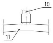
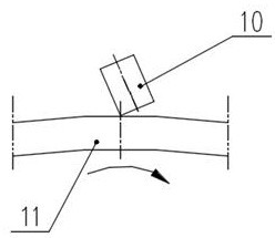
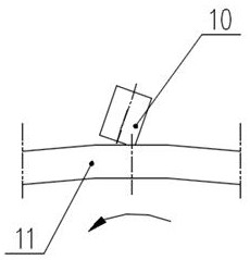
[0026] Such as Figure 4 , 5 , 6, the double-turbine structure of the pumped-storage hydro-generator set provided by this embodiment includes a motor 2 and a rotating shaft 3, the motor 2 is arranged on the upper end of the rotating shaft 3, and the motor 2 is provided with a fixed stator and a rotatable The rotor, the stator and the rotor are arranged together, the rotor is arranged on the upper end of the rotating shaft 3, and rotates with the rotating shaft 3; the slip ring chamber 1 is arranged on the motor 2, and the external electric energy is input into the motor through the contact between the carbon brush 10 and the slip ring 11 2, as the electric energy to drive the motor 2 to rotate; or as the electric energy generated by the generator to output outward through the contact between the carbon brush and the collector ring; on the rotating shaf...


PUM


Abstract

The invention discloses a double-turbine structure of a pumped storage water-turbine generator set. The double-turbine structure comprises a motor and a rotating shaft, the motor is arranged at the top end of the rotating shaft, a fixed stator and a fixed rotor are arranged in the motor, the rotor is arranged at the upper end of the rotating shaft and rotates along with the rotating shaft; a slipring chamber is arranged on the motor in a matched manner; a first turbine and a second turbine are axially arranged on the rotating shaft at an interval, the directions of turbine blades of the firstturbine and the second turbine are opposite, one turbine blade is arranged in the forward direction, the other turbine blade is arranged in the reverse direction; and the first turbine is provided with a first water guide mechanism in a cooperating mode, introduced water makes contact with the turbine blades of the first turbine, the second turbine is provided with a second water guide mechanismin a cooperating mode, and the introduced water makes contact with the turbine blades of the second turbine. According to the double-turbine structure of the pumped storage water-turbine generator set, the motor and the rotating shaft rotate in the same direction during power generation and water pumping, so that the rotating direction of the motor is prevented from being adjusted; power generation and water pumping can be carried out on the same equipment at the same time or in a time-sharing manner; angle deviation of a slip ring and a carbon brush is prevented, the fact that the contact area of the carbon brush and the slip ring is reduced is prevented, and the contact area of the carbon brush and a collector ring is ensured to be within a reasonable range.

Description

technical field [0001] The invention relates to a hydroelectric generating set, in particular to a twin-turbine structure of a pumped storage hydroelectric generating set which can be used not only as a hydroelectric generating set but also as a water pump for pumping water. Background technique [0002] The pumped storage power generation turbine unit is a "peak-shifting and valley-filling" type hydro-generator unit, also known as an energy-storage hydropower station. The pumped storage power station is a hydropower station that uses the electric energy to pump water to the upper reservoir when the power load is low, and then releases water to the lower reservoir to generate electricity during the peak power load period. It can transform the excess electric energy when the grid load is low into high-value electric energy during the peak period of the grid, and is also suitable for FM , phase modulation , stabilize the cycle and voltage of the power system, and should be ...

Claims


Application Information

Patent Timeline
IPC IPC(8): F03B13/06F03B3/16H02K13/00H02K13/10
CPCF03B3/16F03B13/06F05B2220/706H02K13/00H02K13/003H02K13/10Y02E10/20Y02E60/16
Inventor 张宏伟
Owner 重庆华能水电设备制造有限公司
Why Eureka
Try Eureka