
River sediment deposition detection device

A detection device and sediment technology, applied in the direction of measuring device, sampling device, sampling, etc., can solve the problems of sample leakage, affecting the accuracy of sludge samples, and unfavorable detection of sludge samples, etc.

Active Publication Date: 2020-10-20
马东晓
View PDF11 Cites 10 Cited by
  • Summary
  • Abstract
  • Description
  • Claims
  • Application Information

AI Technical Summary

Problems solved by technology

[0003] The existing sludge sample collection equipment usually collects the shallow surface layer of sludge on the water surface through a collector extending into the water, which cannot collect deeper sludge in sections, and the collected sludge cannot maintain the integrity of the section, which is not conducive to later detection For sludge samples, it is very likely that sample leakage or sample dilution will occur during the sampling ascent process, which will affect the accuracy of sludge sample detection

Method used


Image

  • River sediment deposition detection device
  • River sediment deposition detection device
  • River sediment deposition detection device

Examples


Embodiment 1

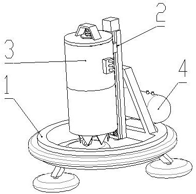
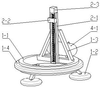
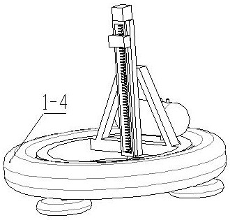
[0035] see Figure 1 to Figure 8 , the present invention provides a river sediment deposition detection device,

[0036] It includes a supporting device 1, a driving device 2 is fixedly arranged on the supporting device 1, and a sampling device 3 for collecting sludge samples is movably connected to the driving device 2, and the driving device 2 drives the sampling device 3 to move in the vertical direction;

[0037] Also includes a storage device 4 for storing compressed air;

[0038] The support device 1 comprises a ring-shaped support frame 1-1 and an array of several legs 1-2 arranged below the support frame 1-1, and a disc-shaped backing plate is arranged below the legs 1-2, and the backing plate can make the device Staying on the silt, no subsidence will occur; a vertical fixing frame 1-3 is fixedly arranged above the supporting frame 1-1, and a driving device 2 is fixedly arranged on one side of the fixing frame 1-3;

[0039] Located on the outside of the support fram...

Embodiment 2

[0059] On the basis of Embodiment 1, it also includes a gas source distributor located on the outer wall of the sampling barrel. The air inlet end of the gas source distributor is detachably connected to the gas pipe, and the other end of the gas pipe is connected to the solenoid valve and the gas cylinder 4-1. The gas source The air outlet end of the distributor is fixedly connected to the air inlets of the two airbags 3-25 through the air pipe, and the air pipe and the sampling device 3 can be separated after the sampling device 3 is removed by disassembling the air pipe and the air source distributor. The sampling device 3 moves to the detection area, and the sludge is taken out for detection of the samples.


PUM


Abstract

The invention discloses a river sediment deposition detection device, relates to the field of water conservancy equipment, and adopts the technical scheme that the river sediment deposition detectiondevice comprises a supporting device, a driving device is fixedly arranged on the supporting device, a sampling device for collecting a sediment sample is movably connected to the driving device, andthe driving device drives the sampling device to move in the vertical direction; the device also comprises a storage device for storing compressed air; the supporting device comprises an annular supporting frame and a plurality of supporting legs arranged below the supporting frame in an array mode, a vertical fixed frame is fixedly arranged above the supporting frame, and a driving device is fixedly arranged on one side of the fixed frame; and a floating-sinking air bag is fixedly connected to the outer side of the supporting frame. The device has the beneficial effects that sludge with different depths can be collected at a time, it can be guaranteed that the collected cross section is complete, the sample detection precision is guaranteed, and data of various heavy metal pollution in different forms of sludge on the same cross section can be more effectively observed; the sludge collection efficiency is high and the use is convenient.

Description

technical field [0001] The invention relates to the field of water conservancy detection equipment, in particular to a river sediment deposition detection device. Background technique [0002] In the study of water pollution, the composition analysis of underwater silt is an important part of water body research, and in some specific studies, samples of underwater silt at different depths are also required to analyze the content of heavy metals and other pollutants. Generally speaking, there are roughly two forms of silt: one is black mud with a high moisture content that cannot be formed, and the other is a relatively loose clay layer mixed with plant residues. [0003] The existing sludge sample collection equipment usually collects the shallow surface layer of sludge on the water surface through the collector extending into the water, which cannot collect deeper sludge in sections, and the collected sludge cannot maintain the integrity of the section, which is not conduci...

Claims


Application Information

Patent Timeline
IPC IPC(8): G01N1/08G01N1/10
CPCG01N1/08G01N1/10G01N2001/1025
Inventor 马东晓刘国凤许文彬郝成章李久勇宫龙飞田保国张营营王志斌
Owner 马东晓
Learn More