Sidelobe suppression method for inter-beam amplitude comparison of multi-beam array

A multi-beam, beam technology, applied in the field of sidelobe suppression of sidelobe suppression

Pending Publication Date: 2020-10-20
中国船舶集团有限公司第七二四研究所
View PDF3 Cites 3 Cited by
  • Summary
  • Abstract
  • Description
  • Claims
  • Application Information

AI Technical Summary

Problems solved by technology

[0005] The purpose of the present invention is to invent a sidelobe suppression method for the inter-beam ratio of the multi-beam digital array, which solves the problem of false signal suppression of the multi-beam digital array system entering the signal from the sidelobe

Method used


Image

  • Sidelobe suppression method for inter-beam amplitude comparison of multi-beam array
  • Sidelobe suppression method for inter-beam amplitude comparison of multi-beam array
  • Sidelobe suppression method for inter-beam amplitude comparison of multi-beam array

Examples


Embodiment Construction

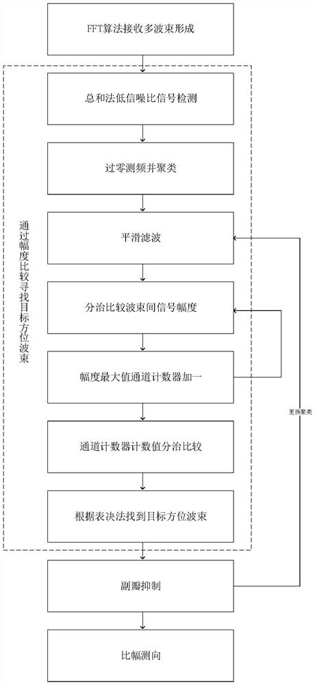
[0030] The present invention proposes a method for suppressing sidelobe of a multi-beam array beam-to-beam ratio, the steps of the embodiment are as follows figure 1 As shown, the details are as follows:

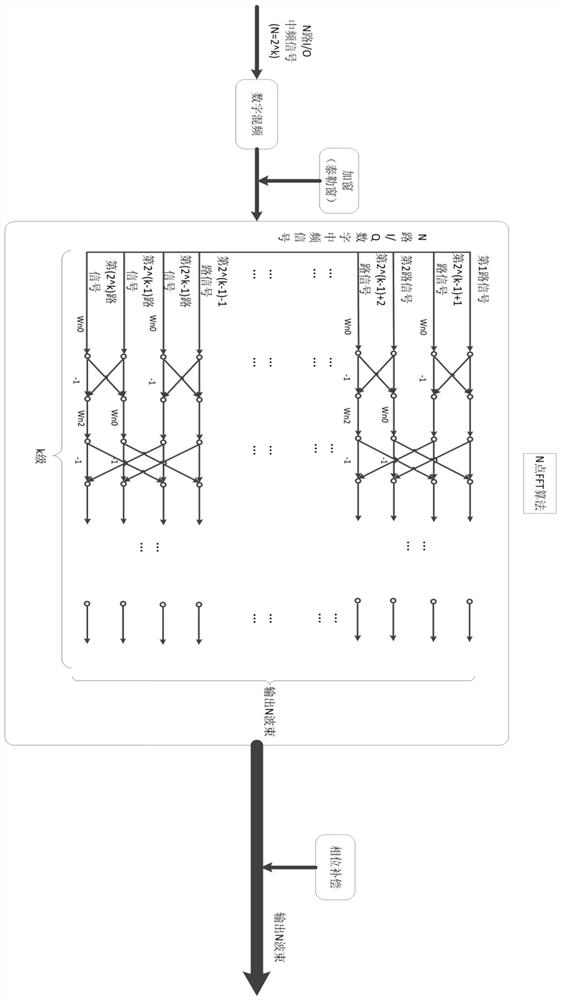
[0031] Step 1. Use the FFT algorithm to realize multi-beam reception.

[0032] This method is based on the fact that the antenna azimuth pattern is the Fourier transform of the current distribution function of the antenna aperture, and there is a Fourier transform pair relationship between the antenna azimuth pattern function and the antenna aperture irradiation function.

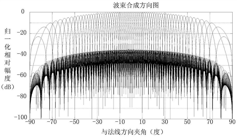
[0033] The signal received by the i-th unit in the N-unit antenna array is in is the spatial phase difference of signals received by adjacent units, and the amplitude weighting coefficient provided to the i-th unit is a ik , the phase compensation is When , the antenna pattern of the linear array can be expressed as where a i =a i0 ·a ik ,like Take the discrete value according to the beam nu...


PUM


Abstract

The invention relates to a sidelobe suppression method for inter-beam amplitude comparison of a multi-beam array. Simultaneous multi-beam coverage of a detection airspace is realized by adopting an FFT method; amplitude comparison is carried out on the detected signals, beams in the target direction are selected from the multiple beams, sidelobe signals deviating from the target direction are suppressed, the target signals which reach different frequencies at the same time and are in different directions can be separated, and accurate direction finding of the target direction is completed in combination with an amplitude comparison direction finding algorithm. The method is high in hardware resource utilization rate, has the characteristic of high target detection orientation accuracy, canalso have a very good effect at a low signal-to-noise ratio, and is particularly suitable for engineering implementation of a broadband digital phased array system.

Description

technical field [0001] This project belongs to the field of radar signal passive detection information processing, and involves a sidelobe suppression method for the ratio of sidelobe suppression between multi-beam simultaneous reception and processing. Background technique [0002] The current detection system DBF technology of the phased array system mainly adopts the digital matching method, which mainly controls the beam scanning by changing the matching value to cover the airspace at a certain angle. However, the multi-beam DBF realized by the FFT method can simultaneously generate multiple beams in a large angle range, and the instantaneous coverage space is large. This method can achieve a better signal detection and interception effect, but it also brings about the problem of more false signals entering from side lobes between multiple beams. [0003] In order to avoid false signals from signals entering from the sidelobe, the traditional method is to add an auxilia...

Claims


Application Information

Patent Timeline
Patent Type & Authority Applications(China)
IPC IPC(8): G01S7/28
CPCG01S7/2813
Inventor 李全越邹正茅玉龙赵紫稷廖卫东
Owner 中国船舶集团有限公司第七二四研究所
Why Eureka
Try Eureka