Vector stepless flux weakening method of permanent magnet synchronous motor
A permanent magnet synchronous motor, vector technology, applied in the electromagnetic field, can solve the problems of small torque loss, easy to run out of control, unable to give full play to the characteristics of permanent magnet synchronous motor, etc.
- Summary
- Abstract
- Description
- Claims
- Application Information
AI Technical Summary
Problems solved by technology
Method used
Image
Examples
Embodiment 1
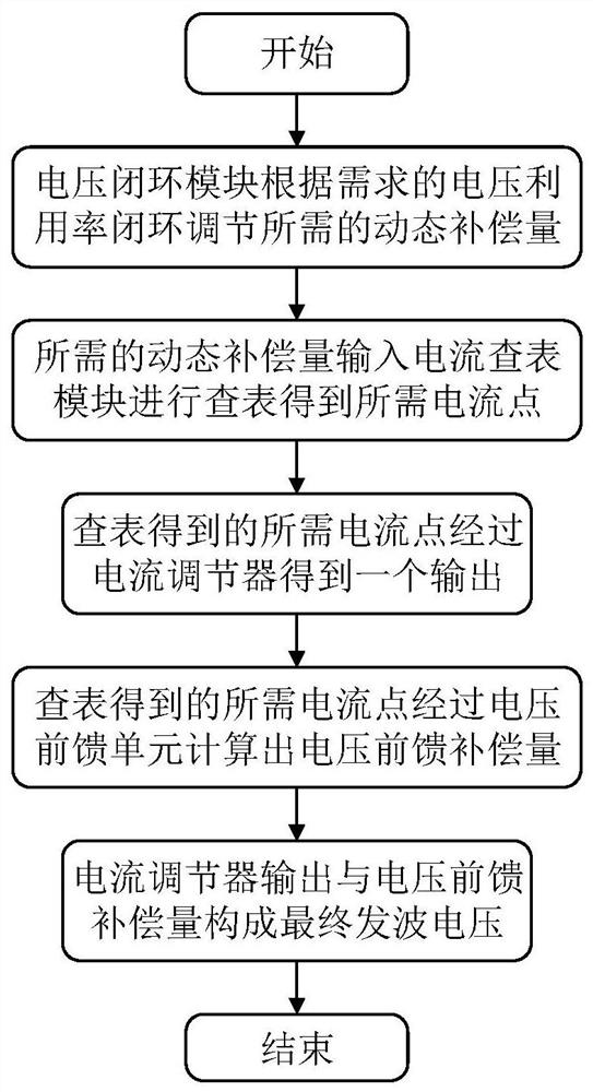
[0056] This embodiment provides a vector stepless field weakening method for permanent magnet synchronous motors, specifically as figure 1 shown, including the following steps:
[0057] S1: The voltage closed-loop module adjusts the required dynamic compensation according to the required voltage utilization rate;
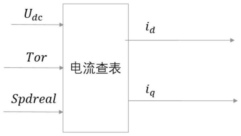
[0058]S2: The required speed compensation is input into the current look-up module to look up the table to obtain the required current point;
[0059] S3: The required current point obtained by looking up the table passes through the current regulator to obtain an output;
[0060] S4: The required current point obtained by looking up the table is calculated through the voltage feedforward unit to calculate the voltage feedforward compensation amount;
[0061] S5: The output of the current regulator and the voltage feed-forward compensation constitute the final wave voltage.
Embodiment 2
[0063] This embodiment provides a vector stepless field weakening method for permanent magnet synchronous motors, such as Figure 2-6 The following steps are shown:
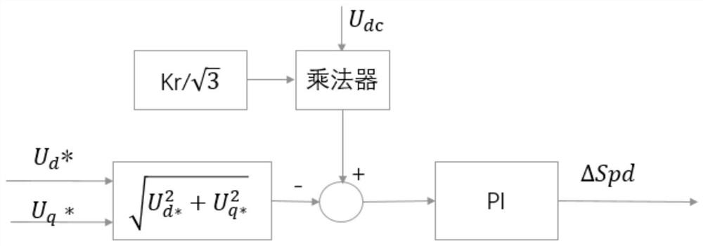
[0064] S1: The voltage closed-loop module adjusts the required dynamic compensation amount according to the required voltage utilization rate.
[0065] Wherein, S1 includes the following steps:
[0066] S11: The voltage closed-loop module sets the current bus voltage U according to the required voltage utilization dc ;
[0067] S12: put U d * and U q * Calculate the arithmetic square root and set the current bus voltage U dc perform linear operations;
[0068] S13: Perform PI calculation on the linear calculation result to obtain the rotational speed compensation amount ΔSpd;
[0069] S14: ΔSpd and the current speed Spd accumulate the output speed Spdreal;
[0070] Among them, Y d * and U q * is the output of the current regulator.
[0071] S2: The required voltage compensation is input to the current ...
PUM
 Abstract
Description
Claims
Application Information
 - R&D
- Intellectual Property
- Life Sciences
- Materials
- Tech Scout
- Unparalleled Data Quality
- Higher Quality Content
- 60% Fewer Hallucinations
Browse by: Latest US Patents, China's latest patents, Technical Efficacy Thesaurus, Application Domain, Technology Topic, Popular Technical Reports.
© 2025 PatSnap. All rights reserved.Legal|Privacy policy|Modern Slavery Act Transparency Statement|Sitemap|About US| Contact US: help@patsnap.com


