Al technical title is built by PatSnap Al team. It summarizes the technical point description of the patent document.
A flying shear control and high-speed technology, which is applied in the direction of tail end control, metal rolling, manufacturing tools, etc., can solve the problems of restricting production line production efficiency and control error
Active Publication Date: 2020-10-23
SGIS SONGSHAN CO LTD
View PDF10 Cites 2 Cited by
Summary
Abstract
Description
Claims
Application Information
AI Technical Summary
This helps you quickly interpret patents by identifying the three key elements:
Problems solved by technology
Method used
Benefits of technology
Problems solved by technology
[0007] In practical application, due to factors such as the stability of on-site detection components, slight fluctuations in the speed of the rolled piece and the speed of the blade, etc., there are often some errors in the control of the steel puller, and the cutt...
Method used
Image
Click on the blue label to locate the original text in one second.
Reading with bidirectional positioning of images and text.
Examples
Embodiment 1
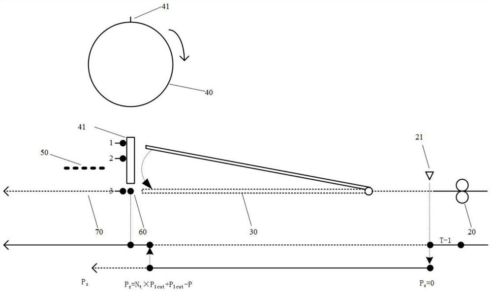
[0041] Such as figure 1 Shown, a kind of high-speed flying shear control method comprises the following steps:
[0042] S1. Use induction devices such as speedometers to detect the speed V of the rolled piece at the sampling stage T-1 r , and according to the velocity V r Calculate the first pulse value P of the forward rotation start of the steel dial 30, the formula is:
[0043] P=T×V r ×P 0 ÷(πD)
[0044] Wherein, T is the time required for the steel puller 30 to move from the broken position 1 to the shear position 2; P 0 is the number of pulses for one revolution of the blade 41; D is the rotation diameter of the blade 41;
[0045] S2. When the rolled piece detection equipment 21 detects the head of the rolled piece, collect the second pulse value P of the blade 41 relative to the intersection point 60 n1, calculate the third pulse value P corresponding to the length between adjacent blades 41 1cut , the formula is:
[0046] P 1cut =(P 0 ×L)÷(πD)
[0047] Wher...
Embodiment 2
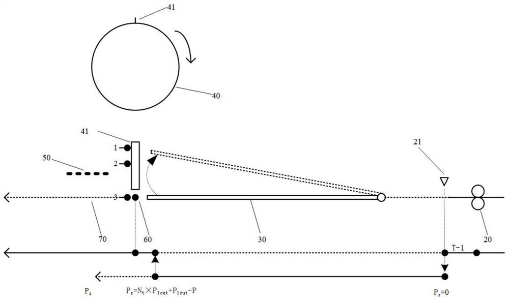
[0059] Such as figure 2 Shown, a kind of high-speed flying shear control method comprises the following steps:
[0060] S1. Use induction devices such as speedometers to detect the speed V of the rolled piece at the sampling stage T-1 r , and according to the velocity V r Calculate the first pulse value P of the reverse start of the steel puller 30, the formula is:
[0061] P=T×V r ×P0÷(πD)
[0062] Wherein, T is the time required for the steel puller 30 to move from the rolling position 3 to the shearing position 2; P 0 is the number of pulses for one revolution of the blade 41; D is the rotation diameter of the blade 41;
[0063] S2. When the rolled piece detection equipment 21 detects the head of the rolled piece, collect the second pulse value P of the blade 41 relative to the intersection point 60 n1 , calculate the third pulse value P corresponding to the length between adjacent blades 41 1cut , the formula is:
[0064] P 1cut =(P 0 ×L)÷(πD)
[0065] Wherein,...
PUM
Abstract
The invention relates to a method for controlling a high-speed flying shear. The method comprises the steps that a first pulse value P of the starting of a steel poker is calculated; a third pulse value P1cut corresponding to the length between adjacent blades is calculated, and blade rotation pulses are accumulated and counted to obtain a fourth pulse value Pz; original blade rotating blade number N1 corresponding to the distance between rolled piece detection equipment and an intersection point, a fifth pulse value delta P1 corresponding to the remaining length, and a sixth pulse value deltaPn1 of the next blade reaching the intersection position are calculated; if the situation that the sixth pulse value delta Pn1 minus the fifth pulse value delta P1 is greater than the first pulse value P is satisfied, the actual blade rotating blade number Nt is equal to the original blade rotating blade number N1; otherwise, the actual blade rotating blade number Nt is equal to the original blade rotating blade number N1 plus 1; and the flying shear is started when the situation that the fourth pulse value Pz is equal to the actual blade rotation blade number Nt multiplied by the third pulsevalue P1cut plus the third pulse value P1cut minus the first pulse value P is satisfied. According to the method for controlling the high-speed flying shear, the accurate control of the steel poker can be achieved, so that the control precision of the high-speed flying shear is improved, the production interruption fault caused by the high-speed flying shear is eliminated, and the production efficiency is greatly improved.
Description
technical field [0001] The invention relates to the technical field of automatic control of high-speed flying shears, more specifically, it relates to a control method of high-speed flying shears. Background technique [0002] In continuous rolling production lines, especially in high-speed wire rod continuous rolling production lines, the speed of high-speed flying shear rolling can reach as high as 100m / s. Operating efficiency is one of the key equipment of high-speed wire rod production line. [0003] High-speed flying shears are generally composed of auxiliary equipment such as rotary cutterheads, steel pullers and partitions. Wherein the shearing blades are fixed on the cutter head, usually 1 pair or 2 pairs or 3 pairs. The steel puller is located upstream of the cutter head, driven and controlled by a high-precision servo system, and its running track is between the breaking position, shearing position and rolling position. Running from the breaking position through...
Claims
Application Information
Patent Timeline
Application Date:The date an application was filed.
Publication Date:The date a patent or application was officially published.
First Publication Date:The earliest publication date of a patent with the same application number.
Issue Date:Publication date of the patent grant document.
PCT Entry Date:The Entry date of PCT National Phase.
Estimated Expiry Date:The statutory expiry date of a patent right according to the Patent Law, and it is the longest term of protection that the patent right can achieve without the termination of the patent right due to other reasons(Term extension factor has been taken into account ).
Invalid Date:Actual expiry date is based on effective date or publication date of legal transaction data of invalid patent.