Tin soldering device and method for circuit board of intelligent home appliance

A circuit board and soldering technology, which is applied in the field of circuit board soldering devices for smart home appliances, can solve the problems that the amount of solder cannot be well controlled, it is difficult to get started, and circuit boards are prone to false soldering.

Inactive Publication Date: 2020-10-23
NANJING BAIYA INTELLIGENT TECH CO LTD
View PDF0 Cites 1 Cited by
  • Summary
  • Abstract
  • Description
  • Claims
  • Application Information

AI Technical Summary

Problems solved by technology

[0003] The purpose of the present invention is to provide a circuit board soldering device for smart home appliances, to solve the problem that the existing spot welding method proposed in the above-mentioned background technology is difficult to get started, and the amount of solder cannot be well controlled, which is prone to false soldering and circuit board soldering. short circuit problem

Method used


Image

  • Tin soldering device and method for circuit board of intelligent home appliance
  • Tin soldering device and method for circuit board of intelligent home appliance

Examples


Embodiment 1

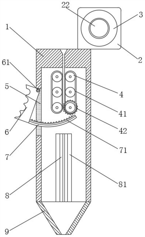
[0021] see Figure 1-2 , the present embodiment provides a circuit board soldering device for smart home appliances, including a hand-held tube 1, a fixing frame 2 with a U-shaped structure is arranged on the top of the holding tube 1, a tin bar tube 3 is installed inside the fixing frame 2, and the holding tube 1. A plurality of rotating rollers 4 are arranged near the top. The outer wall of the hand-held tube 1 is provided with a movable groove 5. The inside of the movable groove 5 is hinged with a pressing plate 6. The bottom end of the pressing plate 6 close to the inner side of the handheld tube 1 is fixed. There is a transmission frame 7, a heating cylinder 8 is installed near the bottom end of the hand-held tube 1, and a discharge port 9 is fixed at the bottom of the hand-held tube 1, and the top of the discharge port 9 extends into the inside of the hand-held tube 1 and is connected with the heating tube 1. The bottom end of cylinder 8 is fixed.

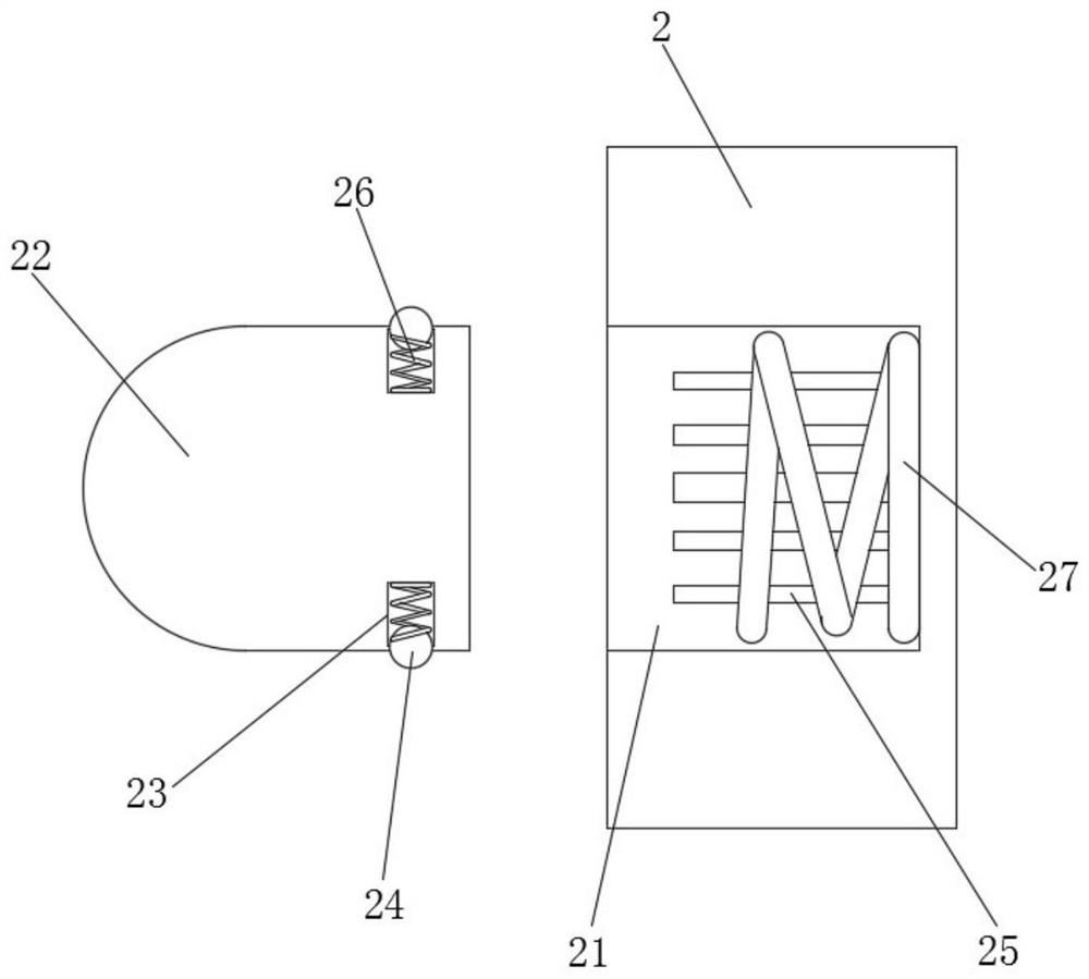
[0022] Fixed frame 2...

Embodiment 2

[0031] see figure 1 , made further improvement on the basis of Embodiment 1: the rotating roller 4 is a waist drum structure, the top view of the transmission frame 7 is a U-shaped structure, the top side of the transmission frame 7 is fixed with a rack 71, and the rack 71 and the gear 42 Mesh, through the U-shaped transmission frame 7 can make the force of the roller 4 more balanced, can make the roller 4 rotate more smoothly, and the drum-shaped roller 4 can increase the contact area with the outer wall of the tin bar, so that the tin bar The transfer inside the handheld tube 1 is smoother.


PUM


Abstract

The invention discloses a tin soldering device and method for a circuit board of an intelligent home appliance. The tin soldering device comprises a handheld barrel; a fixing frame is arranged at thetop end of the handheld barrel, and a tin bar barrel is installed in the fixing frame; a plurality of rotating rollers are arranged at the position, close to the top end, in the handheld barrel; a movable groove is formed in the outer wall of the handheld barrel, a press plate is hinged in the movable groove, and a transmission frame is fixed to the bottom end of one side of the press plate; a heating barrel is installed in the handheld barrel; a discharge port is fixed to the bottom end of the handheld barrel; a movable hole is formed in the center, right facing the side inner wall, of the fixing frame, a compression spring is installed between the inner wall, away from the opening, of the movable hole and a rotating rod, and channels are formed in the inner wall of the movable hole; theouter walls of the two sets of rotating rollers are in sleeved connection with conveyor belts, a gear is fixed to the outer wall of the rotating roller at the bottommost end in the set on the right side, and a rack is fixed to the top side of the transmission frame; and the outer wall of a shaft rod through which the press plate is hinged to the movable groove is in sleeved connection with a torsional spring. Through the cooperative use of the devices, the difficulty of getting started on spot welding can be reduced, and the situation of over-welding or false welding can be avoided.

Description

technical field [0001] The invention relates to the technical field of circuit board soldering equipment, in particular to a circuit board soldering device for smart home appliances. Background technique [0002] At present, the circuit boards for smart home appliances use highly integrated automatic machinery when producing tin, but when the circuit boards need to be repaired, most of the tools used by maintenance personnel are soldering irons and tin bars. This soldering method not only requires Maintenance personnel require high skills, and are prone to excessive or insufficient soldering at spot welding. Therefore, a circuit board soldering device for smart home appliances that is easy to operate and can control the amount of soldering is proposed. Contents of the invention [0003] The purpose of the present invention is to provide a circuit board soldering device for smart home appliances, to solve the problem that the existing spot welding method proposed in the abo...

Claims


Application Information

Patent Timeline
Patent Type & Authority Applications(China)
IPC IPC(8): B23K3/06B23K3/08B23K101/36
CPCB23K3/0607B23K3/08B23K2101/36
Inventor 曹珏
Owner NANJING BAIYA INTELLIGENT TECH CO LTD
Why Eureka
Try Eureka