
Traction wheel intelligent machining system for elevator traction system

An intelligent processing and elevator traction technology, applied in metal processing equipment, manufacturing tools, grinding workpiece supports, etc., can solve problems such as increasing equipment complexity and cost, secondary damage, and inability to take into account the traction wheels.

Active Publication Date: 2020-10-23
SHENZHI ELEVATOR
View PDF10 Cites 0 Cited by
  • Summary
  • Abstract
  • Description
  • Claims
  • Application Information

AI Technical Summary

Problems solved by technology

[0004] 1. Since the traction sheave is a revolving part, it needs to be stably fixed in the process of processing, but the existing traction sheave cannot be fixed stably in the process of processing, and those relatively A stable fixing method also requires a hydraulic device for fixing. On the one hand, this method will increase the complexity and cost of the entire equipment. At the same time, the fixing of the hydraulic device also needs to detect the hydraulic pressure to avoid damage to the pulley. The guide wheel cannot take into account two conditions in terms of fixing;
[0005] 2. The traction wheel will produce a lot of iron filings during the processing and grinding process. If the iron filings cannot be cleaned in time during the process, the iron filings will cause secondary damage when the grinding head grinds the traction wheel next time. Repeatedly, it will lead to The traction wheel can never achieve a good grinding effect, reducing the quality of the product

Method used


Image

  • Traction wheel intelligent machining system for elevator traction system
  • Traction wheel intelligent machining system for elevator traction system
  • Traction wheel intelligent machining system for elevator traction system

Examples


Embodiment Construction

[0029] The embodiments of the present invention are described in detail below with reference to the accompanying drawings, but the present invention can be implemented in many different ways as defined and covered by the claims.

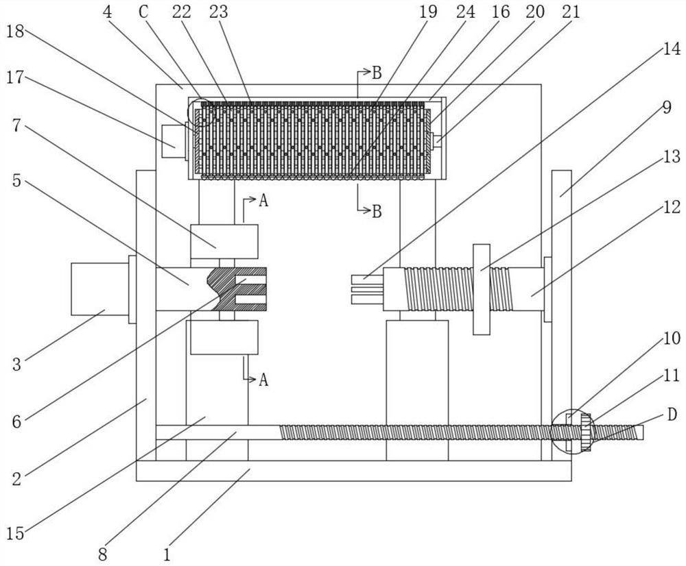
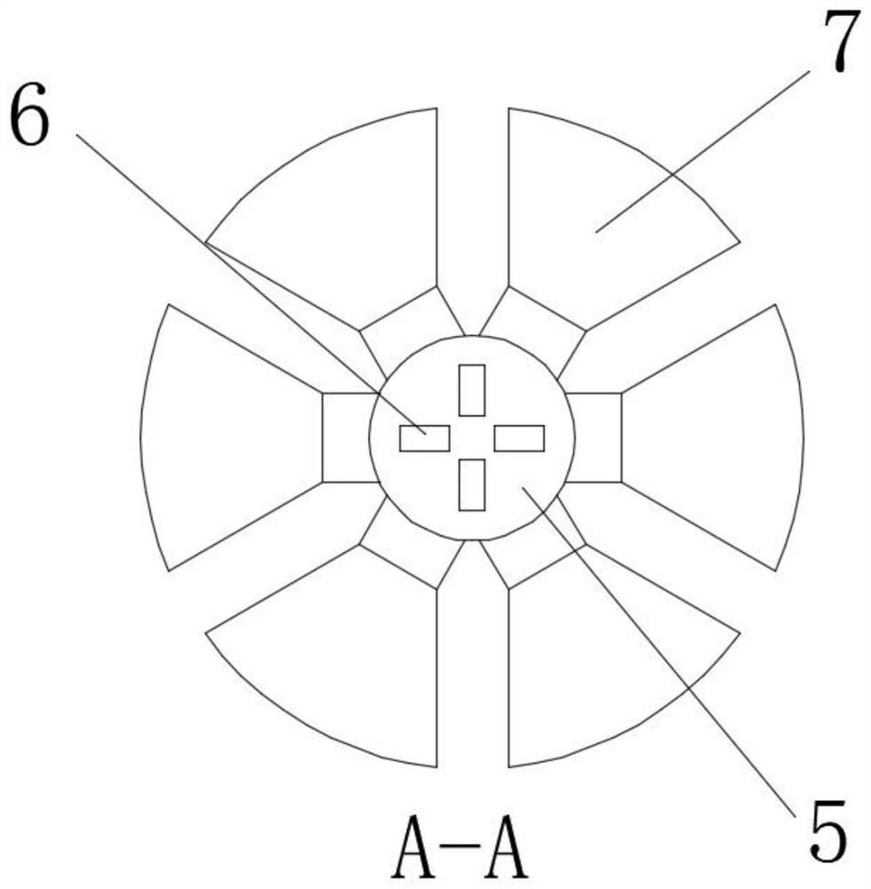
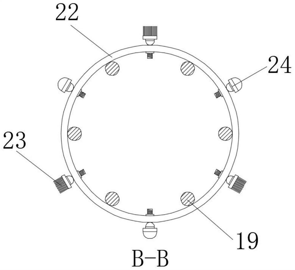
[0030] like Figure 1 to Figure 8 As shown, a traction wheel intelligent processing system for elevator traction system includes a bottom plate 1, a left side plate 2, a back plate 4, a clamping device, a locking device and a grinding device, and the left side plate 2 is fixedly installed on the bottom plate 1 On the left side of the upper surface, the back plate 4 is fixedly installed on the back of the upper surface of the base plate 1, the upper part of the front of the back plate 4 is fixedly installed with a connecting arm, and the left side of the left side plate 2 is fixedly installed with the first motor 3, which is characterized in that: The clamping device is movably installed on the left side of the first motor 3, the locking device is mov...


PUM


Abstract

The invention relates to a traction wheel intelligent machining system for an elevator traction system. The traction wheel intelligent machining system comprises a bottom plate, a left side plate, a back plate, a clamping device, a locking device and a polishing device, wherein the left side plate is fixedly mounted to the left side of the upper surface of the bottom plate, the back plate is fixedly mounted on the back surface of the upper surface of the bottom plate, the upper portion of the front surface of the back plate is fixedly provided with a connecting arm, and the left side of the left side plate is fixedly provided with a first motor. According to the traction wheel intelligent machining system, by means of cooperation of a first fixed rotating shaft and a second fixed rotatingshaft, a traction wheel is sleeved, and then a second screw cap is used for fastening the traction wheel so as to achieve fixing on the traction wheel, and further avoid damaging the traction wheel due to too-tight tightening since the such fastening mode is not achieved by mechanical rotating, so that the fixing on the traction wheel is ensured, and the quality of the traction wheel itself is notaffected.

Description

technical field [0001] The invention relates to the technical field of elevators, in particular to an intelligent processing system for a traction sheave used in an elevator traction system. Background technique [0002] The traction sheave of the elevator is the sheave on the traction machine, also known as the traction sheave or the driving sheave. . [0003] Since the traction sheave needs to bear all the dynamic and static loads of the car, load capacity, counterweight and other devices, the traction sheave is required to have high strength, good toughness, wear resistance and impact resistance, so ductile cast iron is mostly used in the material. The traction pulley is a revolving body part, so the main processing method is mainly turning processing to realize the processing and deburring of the pulling pulley. However, the existing pulling pulley has the following problems in the processing process: [0004] 1. Since the traction wheel is a revolving part, it needs t...

Claims


Application Information

Patent Timeline
IPC IPC(8): B24B5/04B24B41/00B24B41/02B24B41/06B24B47/12B24B47/22B24B55/06
CPCB24B5/04B24B41/062B24B41/02B24B55/06B24B41/00B24B47/22B24B47/12
Inventor 方志兰
Owner SHENZHI ELEVATOR
Learn More