Wooden shovel forming machine
A molding machine and wooden shovel technology, applied in molding/shaping machines, special molding/shaping machines, wood processing equipment, etc., can solve problems such as low production efficiency
- Summary
- Abstract
- Description
- Claims
- Application Information
AI Technical Summary
Problems solved by technology
Method used
Image
Examples
Embodiment 1
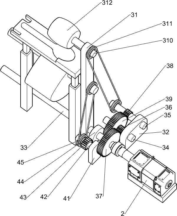
[0041] A wooden shovel forming machine, such as figure 1 As shown, it includes base 1, motor 2, cutting mechanism 3 and ejecting mechanism 4, motor 2 is installed on the left side of base 1, cutting mechanism 3 is installed on the left side of base 1, motor 2 is connected with cutting mechanism 3, and base 1 is left A material jacking mechanism 4 is arranged on the side, and the material jacking mechanism 4 is connected with the cutting mechanism 3 .
[0042] When it is necessary to make a wooden shovel, first place the wooden shovel on the parts of the ejecting mechanism 4, so that the side of the wooden shovel to be cut is located directly below the cutting part of the cutting mechanism 3, then start the motor 2, and the output shaft of the motor 2 drives The cutting part of the cutting mechanism 3 rotates clockwise at a high speed. At the same time, the motor 2 drives the parts of the ejector mechanism 4 to reciprocate intermittently up and down. Speed, when the parts of t...
Embodiment 2
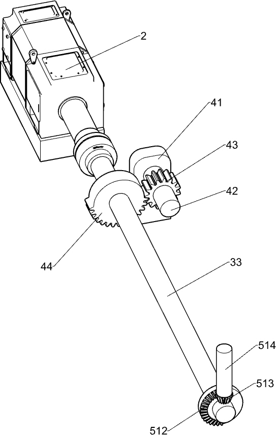
[0044] In particular, as Figure 1-4As shown, the cutting mechanism 3 includes a first support frame 31, a first support seat 32, a transmission shaft 33, a first rotating shaft 34, a second rotating shaft 35, a first small gear 36, a first large gear 37, and a second small gear 38 , the second large gear 39, the output shaft 310, the first belt assembly 311 and the cutting drum 312, the left side of the base 1 is equipped with a first support frame 31, the first support frame 31 is located at the right side of the motor 2, the first support frame 31 The lower part is rotatably provided with a transmission shaft 33, the left end of the transmission shaft 33 is connected with the output shaft of the motor 2, the left front side of the base 1 is provided with a first support seat 32, and the rear side of the first support seat 32 is rotatably connected with a first rotating shaft 34. The first small gear 36 is installed on the left side of a rotating shaft 34, and the left side ...
Embodiment 3
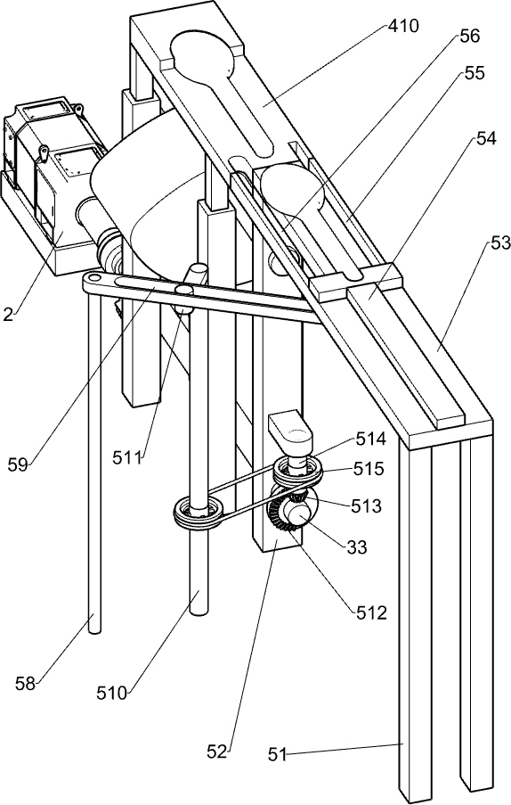
[0049] according to Figure 5-8 As shown, it also includes a pushing mechanism 5 and a blanking mechanism 6. The right side of the base 1 is provided with a pushing mechanism 5, and the rear side of the right part of the base 1 is equipped with a blanking mechanism 6.
[0050] The wooden shovel is placed in the parts of the blanking mechanism 6, the motor 2 is started, the cutting drum 312 cuts the wooden shovel, the working plate 410 moves down and resets, the fourth rotating shaft 46 stops rotating, and the wooden shovel that has been cut is manually removed from the working plate 410, at this time, the parts of the pushing mechanism 5 are engaged, and the parts of the pushing mechanism 5 reciprocate left and right. When the parts of the pushing mechanism 5 move to the left, the wooden shovel at the bottom is moved to the left accordingly Push it onto the working board 410 to realize the automatic loading of the wooden shovel without manually placing the wooden shovel on the...
PUM
 Abstract
Description
Claims
Application Information
 - R&D
- Intellectual Property
- Life Sciences
- Materials
- Tech Scout
- Unparalleled Data Quality
- Higher Quality Content
- 60% Fewer Hallucinations
Browse by: Latest US Patents, China's latest patents, Technical Efficacy Thesaurus, Application Domain, Technology Topic, Popular Technical Reports.
© 2025 PatSnap. All rights reserved.Legal|Privacy policy|Modern Slavery Act Transparency Statement|Sitemap|About US| Contact US: help@patsnap.com


