
Gas compressor-turbine integrated engine

A compressor and engine technology, which is applied in the direction of machines/engines, liquid fuel engines, engine components, etc., can solve the problems of large radial size, low power internal energy, pressure potential energy, and low compression efficiency

Active Publication Date: 2020-10-23
NANCHANG HANGKONG UNIVERSITY
View PDF14 Cites 0 Cited by
  • Summary
  • Abstract
  • Description
  • Claims
  • Application Information

AI Technical Summary

Problems solved by technology

[0002] Centrifugal compressor, as a kind of impeller compressor, is widely used in small and medium-sized gas compressors in the fields of aviation, ships, power generation, etc. Among the turbine engines, but its shortcomings are also obvious, the most prominent is the low gas flow capacity per unit area and compressor efficiency
The main reason for the low gas flow capacity per unit area is that the area of ​​the air inlet is smaller than that of the blades. If the air inlet is still facing the wind, there will be considerable windward resistance; and the main reason for the low compression efficiency is its centrifugal compression. The method makes the air flow leave the compressor at a high speed, and the power provided by the turbine is less used to increase the internal energy and pressure potential energy of the air flow. In addition, the higher air outlet velocity is quite unfavorable for the combustion in the combustion chamber , so the airflow from the centrifugal compressor needs to be additionally decelerated and boosted before entering the combustion chamber, which requires additional structural components, such as diffusers and volutes, and the structural size will be further increased
[0003] The centripetal turbine, as a type of turbine in which the air flow flows radially, has an impeller shape very similar to the centrifugal compressor, and is used because of its simple structure, large reliable working range, and good structural rigidity and strength. In systems that require a compact power source, similar to centrifugal compressors, there are also large radial dimensions and low gas flow capacity per unit area, and there are also large heating areas and cooling problems caused by long turbine flow paths. more demanding issues

Method used


Image

  • Gas compressor-turbine integrated engine
  • Gas compressor-turbine integrated engine
  • Gas compressor-turbine integrated engine

Examples


Embodiment Construction

[0035] The following will clearly and completely describe the technical solutions in the embodiments of the present invention with reference to the accompanying drawings in the embodiments of the present invention. Obviously, the described embodiments are only some, not all, embodiments of the present invention. Based on the embodiments of the present invention, all other embodiments obtained by persons of ordinary skill in the art without making creative efforts belong to the protection scope of the present invention.

[0036] The purpose of the present invention is to provide a compressor-turbine integrated engine, to solve the problems in the prior art, compared with the same intake air volume, the same output power using axial flow compressor and axial flow turbine The gas turbine engine can significantly simplify the structure and reduce the axial size.

[0037] In order to make the above objects, features and advantages of the present invention more comprehensible, the p...


PUM


Abstract

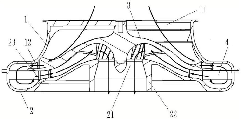
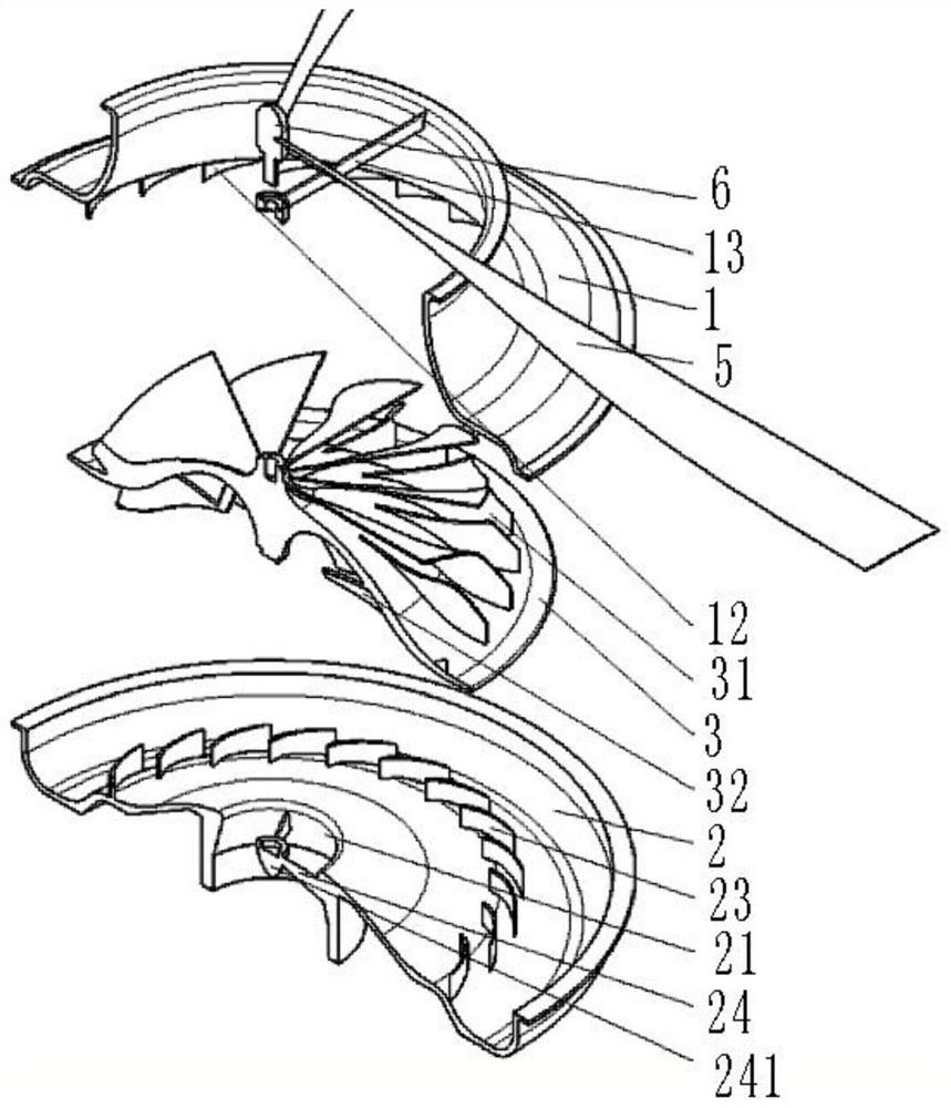
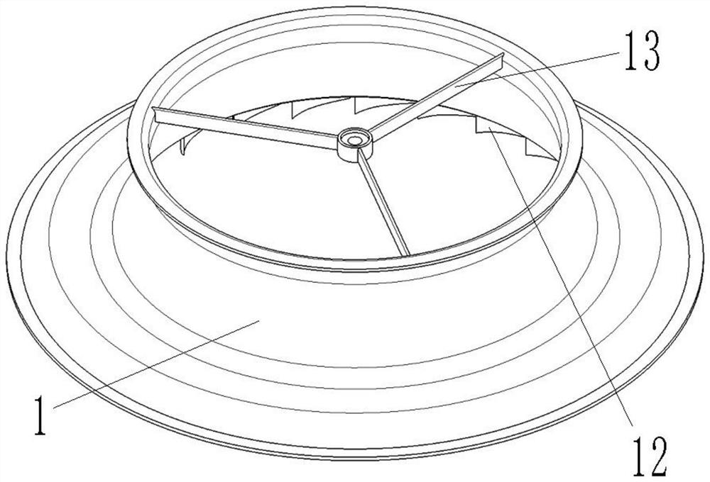
The invention discloses a gas compressor-turbine integrated engine. The gas compressor-turbine integrated engine comprises a shell body and a rotor coaxially arranged in the shell body. The local portion of the shell body protrudes outwards in the radial direction to form an annular space, a combustion chamber is arranged in the annular space, and the edge of the rotor stretches into the annular space. An air inlet and an air outlet are formed in the two ends of the shell body correspondingly. The rotor comprises a first surface oriented to the air inlet side and a second surface oriented to the air outlet side. Centrifugal gas compressor blades are arranged on the first surface, and the second surface is provided with radial turbine blades. After airflow comes in from the air inlet, the airflow flows through the first surface, then after the airflow flows back in the combustion chamber, the airflow flows through the second surface, and finally the airflow is exhausted from the air outlet. Compared with a gas turbine engine adopting an axial flow type gas compressor and an axial flow turbine and adopting the same air inflow and the same output power, the structure can be remarkablysimplified, and the axial size can be reduced.

Description

technical field [0001] The invention relates to the field of engines, in particular to a compressor-turbine integrated engine. Background technique [0002] As a kind of impeller compressor, the centrifugal compressor is widely used in small and medium-sized gas compressors in aviation, shipbuilding, power generation and other fields due to its advantages such as high single-stage boosting ratio, wide stable working range, simple structure, and easy maintenance. Among the turbine engines, but its disadvantages are also obvious, the most prominent is the low gas flow capacity per unit area and compressor efficiency. The main reason for the low gas flow capacity per unit area is that the area of ​​the air inlet is smaller than that of the blades. If the air inlet is still facing the wind, there will be considerable windward resistance; and the main reason for the low compression efficiency is its centrifugal compression. The method makes the airflow leave the compressor still...

Claims


Application Information

Patent Timeline
Patent Type & Authority Applications(China)
IPC IPC(8): F01D5/04F01D25/24F04D17/10F04D29/44
CPCF01D5/043F01D25/24F04D17/10F04D29/441
Inventor 皇甫乃章杨蓓胡瑜轩王云张洋洋涂喻昕
Owner NANCHANG HANGKONG UNIVERSITY
Learn More