Screw type vacuum pump with high vacuum degree

A high vacuum, vacuum pump technology, used in rotary piston pumps, pumps, rotary piston/swing piston pump components, etc., can solve the problem of not ensuring the heat dissipation function of the pump body, increasing power, space and maintenance, loss of vacuum effects, etc.

Inactive Publication Date: 2020-10-23
王顺朝
View PDF2 Cites 1 Cited by
  • Summary
  • Abstract
  • Description
  • Claims
  • Application Information

AI Technical Summary

Problems solved by technology

[0002] The screw vacuum pump is a pumping device that uses a pair of screws to perform synchronous high-speed reverse rotation in the pump casing to generate air suction and exhaust. Since the equal-pitch screw pump has no internal compression process, the exhaust temperature is very high, such as cooling If the effect is not good, it will cause deformation of the rotor and casing, which will affect the air extraction effect. Cooling the casing is an essential link
[0003] The existing patent No. CN104329257A proposes a screw rotor cooling device for a screw vacuum pump. By forming a cooling liquid channel inside the helical teeth of the screw rotor, it is ensured that the cooling effect of the screw rotor is better. However, in order to ensure a high vacuum degree, the vacuum pump will use the entire The pump body is completely sealed, and the coolant channel set by the above-mentioned device extends inside the pump body and the port communicates with the coolant tank. If there are micro cracks or deformations in the coolant channel, the pump body loses its sealing and vacuum effect, which will cause Directly affect the vacuum pump and even the surrounding equipment and environment, resulting in an increase in the risk of using the vacuum pump
[0004] The existing patent No. CN105386972A proposes a screw vacuum pump with a dynamic sealing structure. By using a cooling sleeve to form a heat insulating layer between the shaft and the rotor, it blocks the transfer of temperature to the shaft seal at the exhaust end, but it only guarantees the heat insulation function. , without ensuring the heat dissipation function of the pump body, the heat accumulated in the pump body will be difficult to dissipate, and the heat will directly affect the screw, thereby affecting the vacuum formation and other functions in the pump body, which is not conducive to the use of vacuum pumps that require high vacuum
[0005] The existing vacuum pump treatment methods on the market mostly inject cooling water into the vacuum pump casing, and then use the circulating pump and control mechanism to circulate the cooling water to cool down, but the additional circulating pump and control mechanism directly greatly increase the vacuum pump installation environment. Requirements for power, space and maintenance, etc., and increase the maintenance cost of the vacuum pump

Method used


Image

  • Screw type vacuum pump with high vacuum degree
  • Screw type vacuum pump with high vacuum degree
  • Screw type vacuum pump with high vacuum degree

Examples


Embodiment 1

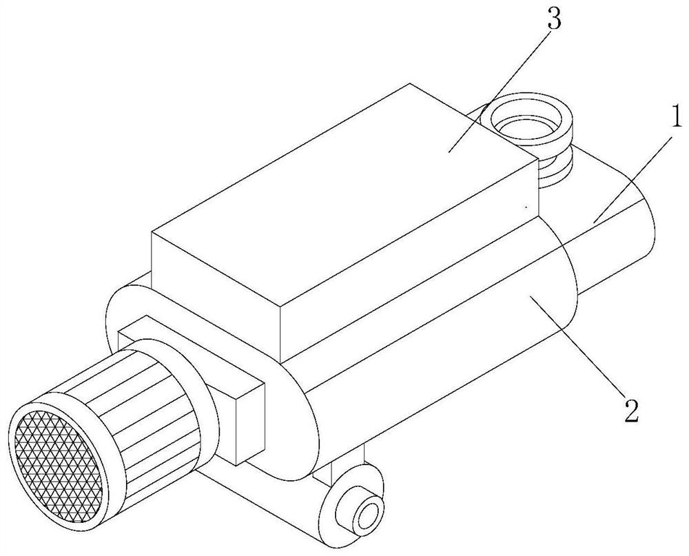
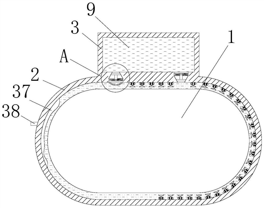
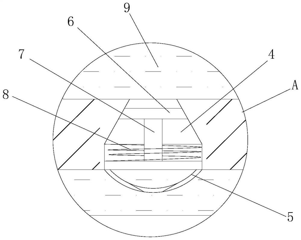
[0034] Example 1: Please refer to Figure 1-5 , a high-vacuum screw type vacuum pump, including a vacuum pump body 1, a casing 2 and a circulation box 3, the casing 2 is sleeved on the outer wall of the vacuum pump body 1, the inner wall of the casing 2 is hollowed out and is separated from the outer wall of the vacuum pump body 1 by five centimeters , the top surface of the shell 2 is fixedly connected with the circulation box 3, the circulation box 3 is a hollow rectangular body, the two sides of the bottom surface of the circulation box 3 are provided with flow holes 4, and the two flow holes 4 are connected with the inside of the shell 2, The circulation hole 4 is a circular platform hole, the side of the left circulation hole 4 with a small diameter faces upwards, and the right circulation hole 4 has a small diameter facing downwards, the inner wall of the circulation hole 4 is fixedly connected with a return spring A8, and the return spring A8 is not far away from the cir...

Embodiment 2

[0035] Example 2: Please refer to Figure 5 , on the basis of Embodiment 1, the front of the circulation box 3 is provided with a round hole and a rotating bearing is fixedly installed in the hole, and the inner ring of the rotating bearing is fixedly connected with a heat dissipation column 20. The material of the heat dissipation column 20 is copper material, and the heat dissipation column 20 is located at the outer wall of the circulation box 3 and is fixedly connected with a heat sink. Through the setting of the heat dissipation column 20, the good thermal conductivity of the copper material of the heat dissipation column 20 is used. After heat exchange between the heat dissipation column 20 and the cooling water 9 in the circulation box 3, the The heat is directly dissipated into the outside air, thereby improving the cooling efficiency of the cooling water 9 in the circulation box 3, ensuring the cooling effect of the cooling water 9 in the casing 2 after circulation, an...

Embodiment 3

[0036] Example 3: Please refer to Figure 6-10 , on the basis of Embodiment 2, the middle inner wall of the circulation box 3 is fixedly connected with a guide ring 21, the guide ring 21 is a hollow cylinder and both sides are provided with openings, the opening on the right side of the guide ring 21 is located at the lower right, and the guide ring 21 is located at the bottom right. The opening on the left side of the ring 21 is located at the upper left, and the cooling column 20 is located at the center of the guide ring 21. The outer wall of the cooling column 20 is fixedly connected with six slide plates 22 at equal intervals. The end of the slide plate 22 away from the cooling column 20 is attached to the inner wall of the guide ring 21. , the cooling water 9 that is squeezed and poured into the circulation box 3 will first be squeezed into the guide ring 21, and through the oblique opening in the guide ring 21, it will generate oblique propulsion to the slide plate 22, a...


PUM


Abstract

The invention relates to the technical field of vacuum pumps, and discloses a screw type vacuum pump with high vacuum degree. The screw type vacuum pump comprises a vacuum pump body, a shell and a circulating box, wherein the shell is connected to the outer wall of the vacuum pump body in a sleeving mode, the top face of the shell is fixedly connected with the circulating box, and the gap betweenthe shell and the vacuum pump body and the circulating box are filled with cooling water. Through arrangement of the shell, the vacuum pump body is cooled by utilizing a way of packaging cooling waterin the shell, and the vacuum degree of the vacuum pump body cannot be affected; through arrangement of a cylinder A, expansion generated after the cooling water absorbs heat is used as power to pushthe cooling water to flow in the shell and to be circularly replaced with the cooling water in the circulating box, thereby maintaining that the temperature of the cooling water in the shell is kept to be always lower than that of the vacuum pump body; the cooling effect of the vacuum pump body is improved by ensuring the heat exchange function of the cooling water, a circulating pump and a control circuit do not need to be additionally arranged for the circulating effect, and the limit on mounting environment of the pump body is reduced.

Description

technical field [0001] The invention relates to the technical field of vacuum pumps, in particular to a high-vacuum degree screw vacuum pump. Background technique [0002] The screw vacuum pump is a pumping device that uses a pair of screws to perform synchronous high-speed reverse rotation in the pump casing to generate air suction and exhaust. Since the equal-pitch screw pump has no internal compression process, the exhaust temperature is very high, such as cooling If the effect is not good, it will cause deformation of the rotor and casing, which will affect the air extraction effect. Cooling the casing is an essential link. [0003] The existing patent No. CN104329257A proposes a screw rotor cooling device for a screw vacuum pump. By forming a cooling liquid channel inside the helical teeth of the screw rotor, it is ensured that the cooling effect of the screw rotor is better. However, in order to ensure a high vacuum degree, the vacuum pump will use the entire The pump...

Claims


Application Information

Patent Timeline
Patent Type & Authority Applications(China)
IPC IPC(8): F04C29/04F04C18/16F04C29/00
CPCF04C18/086F04C18/16F04C29/04F04C2240/30
Inventor 王顺朝
Owner 王顺朝
Why Eureka
Try Eureka