Supercharge Your Innovation With Domain-Expert AI Agents!

Hydraulic control system of dual-clutch transmission

A technology of hydraulic control system and dual-clutch transmission, which is applied in the direction of transmission control, components with teeth, fluid pressure actuation device, etc., and can solve the problem of loss of transmission shift function and other problems

Active Publication Date: 2020-10-23
CHINA FIRST AUTOMOBILE
View PDF6 Cites 0 Cited by
  • Summary
  • Abstract
  • Description
  • Claims
  • Application Information

AI Technical Summary

Problems solved by technology

[0003] The purpose of the present invention is to provide a hydraulic control system of a dual-clutch transmission to solve the problem of partial or complete loss of transmission shifting function caused by the failure of the shift pressure regulating valve

Method used


Image

  • Hydraulic control system of dual-clutch transmission
  • Hydraulic control system of dual-clutch transmission
  • Hydraulic control system of dual-clutch transmission

Examples


Embodiment 1

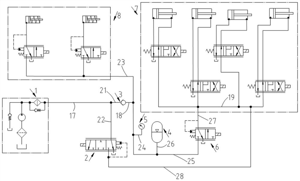
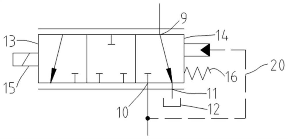
[0033] figure 1 It is the connection relationship diagram of the hydraulic control system of the dual-clutch transmission of the present embodiment, figure 2 Is the schematic diagram of the main oil pressure regulating valve.

[0034] The hydraulic control system of dual clutch transmission includes: oil supply device 1, main oil pressure regulating valve 2, check valve 3, accumulator 4, pressure sensor 5, shift pressure regulating valve 6, gear selection device 7 and clutch control device 8.

[0035] The main oil pressure regulating valve 2 is configured as a three-position three-way valve. The first interface 9 is connected to the oil supply device 1 through the second oil supply branch 22 and the oil supply hydraulic pipeline 17. The second interface 10 is connected to the oil supply device 1 through the second shift pressure The pipeline 28 and the gear selection device supply hydraulic pipeline 19 are connected to the gear selection device 7 , and the third interface 1...

Embodiment 2

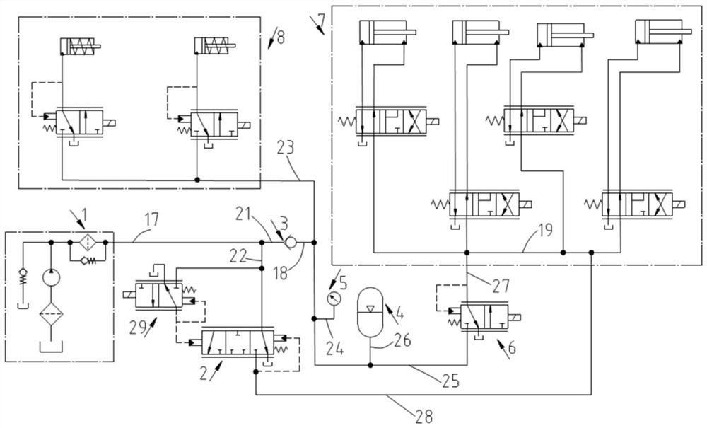
[0046] image 3 It is a connection relationship diagram of the hydraulic control system of the dual-clutch transmission according to the second embodiment of the present application. The difference from Embodiment 1 is that the main oil pressure regulating valve 2 is controlled by a pilot solenoid valve 29 . The pilot solenoid valve 29 is preferably a proportional pressure regulating valve. By adjusting the current size input to the pilot solenoid valve 29, the output oil pressure of the pilot solenoid valve 29 (that is, the force acting on the first valve surface 13) can be adjusted, and then The main oil pressure regulating valve 2 can be placed in the right position, the middle position or the left position according to the demand, and the oil pressure adjustment of the second shift pressure line 28 can also be realized when the main oil pressure regulating valve 2 is in the left position. .


PUM


Abstract

The invention belongs to the technical field of automobile transmissions and discloses a hydraulic control system of a dual-clutch transmission. The hydraulic control system comprises an oil supply device, a gear selection device, a clutch control device and a main oil pressure regulation valve, wherein the oil supply device is equipped with a first oil supply branch and a second oil supply branchwhich are connected in parallel; the first oil supply branch is connected with a main oil pressure pipeline; the gear selection device and the clutch control device are parallelly connected with themain oil pressure pipeline; a pressure sensor is arranged between the main oil pressure pipeline and the gear selection device; the main oil pressure regulation valve is equipped with a first interface, a second interface and a third interface; the first interface communicates with the oil supply device through the second oil supply branch; the second interface communicates with the gear selectiondevice; the third interface communicates with an oil tank; and the main oil pressure regulation valve is capable of selectively closing the second interface and / or the third interface according to the pressure signal of the pressure sensor. When a gear shift pressure regulation valve fails, the first interface and the second interface communicate, hydraulic oil supplied by the oil supply device enters the gear selection device, the corresponding gear is activated by the gear selection device according to the gear demand, and then the emergency gear shift function is achieved.

Description

technical field [0001] The invention relates to the technical field of automobile transmissions, in particular to a hydraulic control system of a dual-clutch transmission. Background technique [0002] The shifting operation of most dual-clutch automatic transmissions adopts hydraulic control. In order to achieve precise shift control and reduce shifting impact, most hydraulic control systems use "single pressure regulating valve to control shifting pressure + several flow regulating valves to control shifting." If the pressure regulating valve fails during use, the shifting function of the transmission will be lost; there are also individual plans that use an additional safety valve to realize emergency shifting of some gears, and the transmission loses power to shift gears at this time Function (partial shifting function is lost), and additional safety valve will lead to increased cost and increased structural size. Contents of the invention [0003] The purpose of the ...

Claims


Application Information

Patent Timeline
Patent Type & Authority Applications(China)
IPC IPC(8): F16H61/02F16H61/12F15B11/16F15B1/02
CPCF16H61/0267F16H61/0276F16H61/12F15B11/16F15B1/02F16H2061/0046F16H2061/1264F16H2061/1224F16H2061/1232F15B2211/8752F15B2211/8636
Inventor 宋建军唐立中陈建勋樊雪来毛泽贤金星月叶珂羽
Owner CHINA FIRST AUTOMOBILE
Features
  • R&D
  • Intellectual Property
  • Life Sciences
  • Materials
  • Tech Scout
  • Unparalleled Data Quality
  • Higher Quality Content
  • 60% Fewer Hallucinations
Learn More