Clamping mechanism and detection device

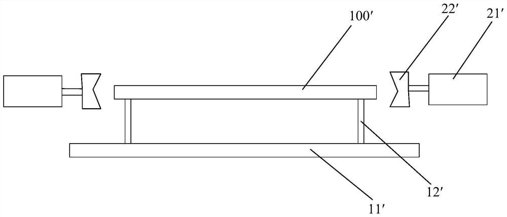
A clamping mechanism and substrate technology, applied in the direction of measuring devices, instruments, etc., can solve the problems of large space occupation, substrate deformation, complex structure, etc.

Active Publication Date: 2020-10-23
SHANGHAI PRECISION MEASUREMENT SEMICON TECH INC
View PDF7 Cites 4 Cited by
  • Summary
  • Abstract
  • Description
  • Claims
  • Application Information

AI Technical Summary

Problems solved by technology

[0007] But this clamping mechanism has the following problems: 1) in order to ensure that the substrate is not easy to loosen when it is in a vertical posture, the chuck needs to apply a large clamping force to generate enough static friction with the substrate to overcome gravity, and Larger clamping forces can cause defor

Method used


Image

  • Clamping mechanism and detection device
  • Clamping mechanism and detection device
  • Clamping mechanism and detection device

Examples


Embodiment 1

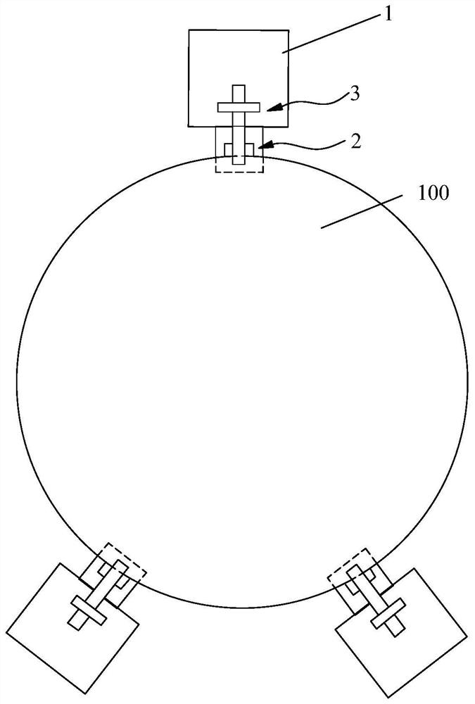
[0062] This embodiment takes the substrate as a wafer as an example for illustration, as figure 2 and 3 As shown, the clamping mechanism includes a support body 1 , an axial pressing assembly 3 and at least three sets of radial pressing assemblies 2 . Wherein, the support body 1 can be an integral plate structure, or a plurality of block structures arranged at intervals, or a frame mechanism, etc. In this embodiment, the support body 1 is a block structure, and each group of radially resisting The pressing assembly 2 is correspondingly connected with a supporting body 1 . The support body 1 includes a support plane 11, the support plane 11 can be used to support the bottom surface of the wafer 100, the radial pressing assembly 2 is arranged on the support body 1 and can respectively press the circumference of the wafer 100 along the radial direction of the wafer 100 surface, to define the radial position of the wafer 100 in the support plane 11, the axial pressing assembly ...

Embodiment 2

[0079] The difference between this embodiment and Embodiment 1 is that in order to realize the axial pressing assembly 3 pressing the wafer 100 in the axial direction, as Figure 6 As shown, the driving member 33 is a single-acting reset cylinder, and the output end of the single-acting reset cylinder is hinged to the end of the pressure rod 32 away from the base plate through a flexible hinge. In this embodiment, when the single-acting reset cylinder is in the initial state, its output end makes the pressure rod 32 in a downward position. Rotate to the avoidance position, when the wafer 100 is placed on the support plane 11, the single-acting reset cylinder is deflated, and the output end is stretched out under the action of the reset element inside it, so that the pressing rod 32 can return to compress the wafer. Circle 100 press down position.

Embodiment 3

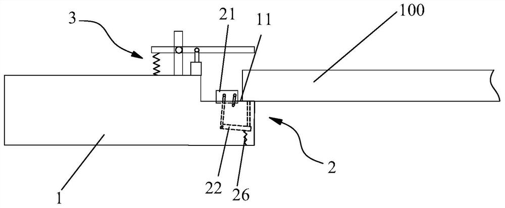
[0081] The difference between this embodiment and Embodiment 1 lies in that, in order to realize that the radial pressing assembly 2 presses the wafer 100 in the radial direction, as Figure 7 As shown, the support body 1 includes a first support block 12 and a second support block 13, the support plane 11 is arranged on the first support block 12, and the first support block 12 and the second support block 13 are along a direction perpendicular to the support plane 11 Sliding fit; the second end of the transmission assembly 22 is provided with a bump 25, and the bump 25 is located between the first support block 12 and the second support block 13; the wafer 100 is placed on the support plane 11 so that the first support block 12 Close to the second supporting block 13 and press down the protrusion 25 . When the wafer 100 is placed on the support plane 11 of the first support block 12, under the gravity of the wafer 100, the first support block 12 slides downward relative to t...


PUM


Abstract

The invention relates to the technical field of substrate detection and discloses a clamping mechanism and a detection device. The clamping mechanism is used for clamping a substrate and comprises a supporting body, at least three sets of radial abutting assemblies and axial abutting assemblies, wherein the supporting body comprises a supporting plane, the supporting plane is used for supporting abottom surface of the base plate, the at least three groups of radial pressing assemblies are arranged on the supporting body and can respectively press a peripheral surface of the substrate along the radial direction of the substrate so as to limit the position of the substrate in the supporting plane, the axial abutting assembly is arranged on the supporting body, and the axial abutting assembly can clamp the substrate to the supporting plane in the axial direction of the substrate e. The substrate clamping process of the clamping mechanism is simple, positioning precision is high, and damage to the substrate cannot be caused. According to the detection device, the substrate clamping step can be simplified and measurement accuracy of the substrate can be improved by adopting the clamping mechanism.

Description

technical field [0001] The invention relates to the technical field of substrate detection, in particular to a clamping mechanism and a detection device. Background technique [0002] In order to form a target product based on substrate processing, it is necessary to obtain the surface topography information of the substrate in advance. Based on the surface topography information, the preset process is completed on the substrate, and the target product is finally obtained. [0003] Taking the substrate as a wafer as an example, in the wafer production or chip manufacturing process, the wafer often has morphology changes. For example, in processes such as coating, etching, chemical mechanical polishing or heat treatment, the surface morphology of the wafer may be If such a change in shape is not known in processes such as lithography, adaptive adjustments cannot be made according to the change in shape, and the change in surface shape of the wafer will not be conducive to ac...

Claims


Application Information

Patent Timeline
IPC IPC(8): G01B21/20
CPCG01B21/20
Inventor 陈梦来
Owner SHANGHAI PRECISION MEASUREMENT SEMICON TECH INC
Why Eureka
Try Eureka