
Printed electronic device and manufacturing method, manufacturing equipment and assembly line thereof

A technology of printed electronics and manufacturing methods, applied in the field of additive manufacturing, can solve problems such as poor missile performance and high resistance

Pending Publication Date: 2020-10-23
BEIJING DREAM INK TECH CO LTD
View PDF0 Cites 1 Cited by
  • Summary
  • Abstract
  • Description
  • Claims
  • Application Information

AI Technical Summary

Problems solved by technology

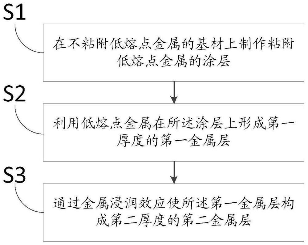
[0004] In view of this, an object of the present invention is to propose a method for manufacturing printed electronics to solve the problem that the low-melting-point metal printed electronics produced by the equipment in the prior art is too thin, resulting in a large resistance and poor missile performance.

Method used


Image

  • Printed electronic device and manufacturing method, manufacturing equipment and assembly line thereof
  • Printed electronic device and manufacturing method, manufacturing equipment and assembly line thereof
  • Printed electronic device and manufacturing method, manufacturing equipment and assembly line thereof

Examples


Embodiment Construction

[0022] The following description and drawings illustrate specific embodiments of the invention sufficiently to enable those skilled in the art to practice them. Other embodiments may incorporate structural, logical, electrical, process, and other changes. The examples merely represent possible variations. Individual components and functions are optional unless explicitly required, and the order of operations may vary. Portions and features of some embodiments may be included in or substituted for those of other embodiments. The scope of embodiments of the present invention includes the full scope of the claims, and all available equivalents of the claims. These embodiments of the present invention may be referred to herein, individually or collectively, by the term "invention", which is for convenience only and is not intended to automatically limit the application if in fact more than one invention is disclosed The scope is any individual invention or inventive concept.

...


PUM

PropertyMeasurementUnit
First thicknessaaaaaaaaaa
Second thicknessaaaaaaaaaa

Abstract

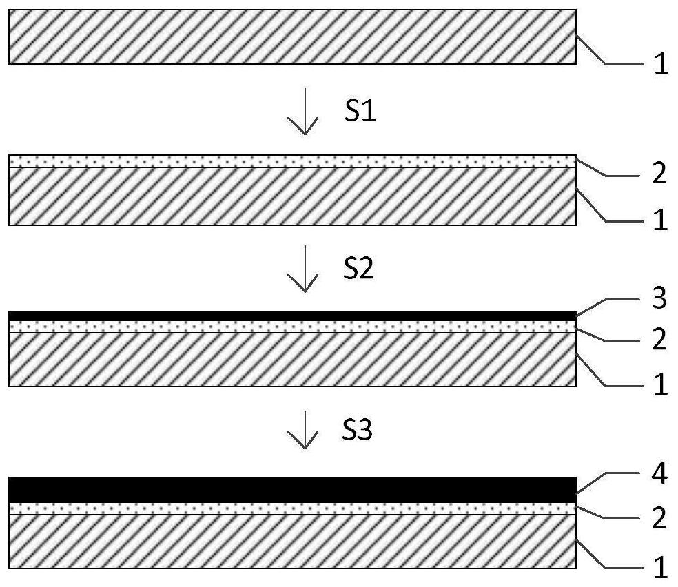
The embodiment of the invention discloses a printed electronic device and a manufacturing method, manufacturing equipment and an assembly line thereof, and relates to the technical field of printed electronic additive manufacturing. The manufacturing method of the printed electronics comprises the following steps: manufacturing a coating adhered with low-melting-point metal on a base material notadhered with the low-melting-point metal, wherein the pattern of the coating is consistent with that of a target printed electron; forming a first metal layer with a first thickness on the coating byutilizing low-melting-point metal, and enabling the first metal layer to become a second metal layer with a second thickness through a metal infiltration effect, wherein the second thickness is greater than the first thickness. According to the invention, the metal infiltration effect between the low-melting-point metal and the low-melting-point metal is utilized to thicken the low-melting-point metal printed electrons, so that the defects of high resistance and poor conductivity caused by too thin low-melting-point metal printed electrons are effectively overcome.

Description

technical field [0001] The invention belongs to the technical field of additive manufacturing, and in particular relates to a printed electronics, its manufacturing method, its manufacturing equipment and its assembly line. Background technique [0002] Printed electronics is an emerging process technology that applies traditional printing (or coating) processes to the manufacture of electronic components and products. Electronic paste is one of the basic materials in the printed electronics industry. Among them, conductive paste mainly includes silver paste, aluminum paste, gold paste, copper paste, etc., which are widely used in front and back electrodes of solar panels, RFID electronic tags, mobile phones, etc. Antennas, non-contact IC card antenna lines and many other fields. However, the metal components of the above-mentioned conductive pastes all have relatively high melting points, and after sintering, the conductive phase is still in contact with particles, so the ...

Claims


Application Information

Patent Timeline
IPC IPC(8): H01B13/00H05K3/12H01Q1/38
CPCH01B13/0026H01Q1/38H05K3/12
Inventor 卢双豪
Owner BEIJING DREAM INK TECH CO LTD
Learn More