
Outdoor rainproof power cabinet

A power cabinet, outdoor technology, applied in the field of power cabinets, can solve problems such as poor heat dissipation performance of power cabinets

Active Publication Date: 2020-10-23
牡丹江鸿鑫设备制造有限公司
View PDF11 Cites 6 Cited by
  • Summary
  • Abstract
  • Description
  • Claims
  • Application Information

AI Technical Summary

Problems solved by technology

Especially in windy and windy weather, the horizontal airflow easily entrains rainwater into the power cabinet. For this reason, rainproof covers are often installed at the cooling holes of the power cabinet to block rainwater, but also block the interaction of air inside and outside the power cabinet. Poor cooling performance of the power cabinet

Method used


Image

  • Outdoor rainproof power cabinet
  • Outdoor rainproof power cabinet
  • Outdoor rainproof power cabinet

Examples


Embodiment 1

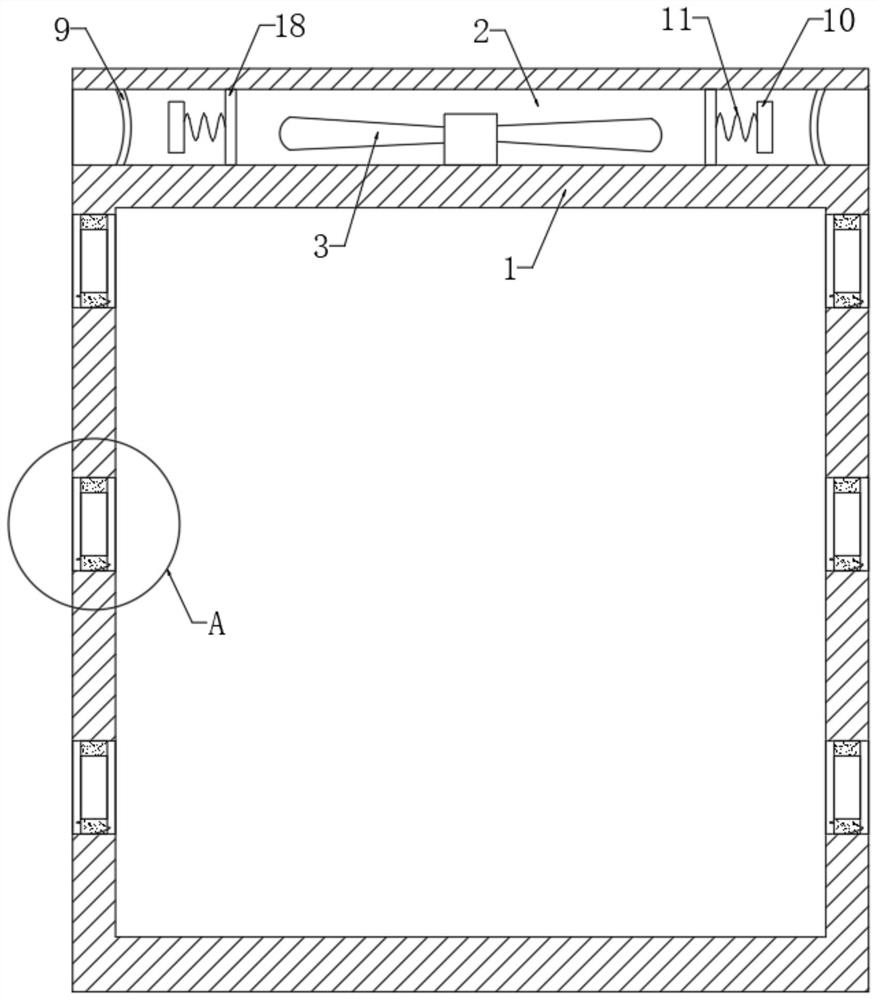
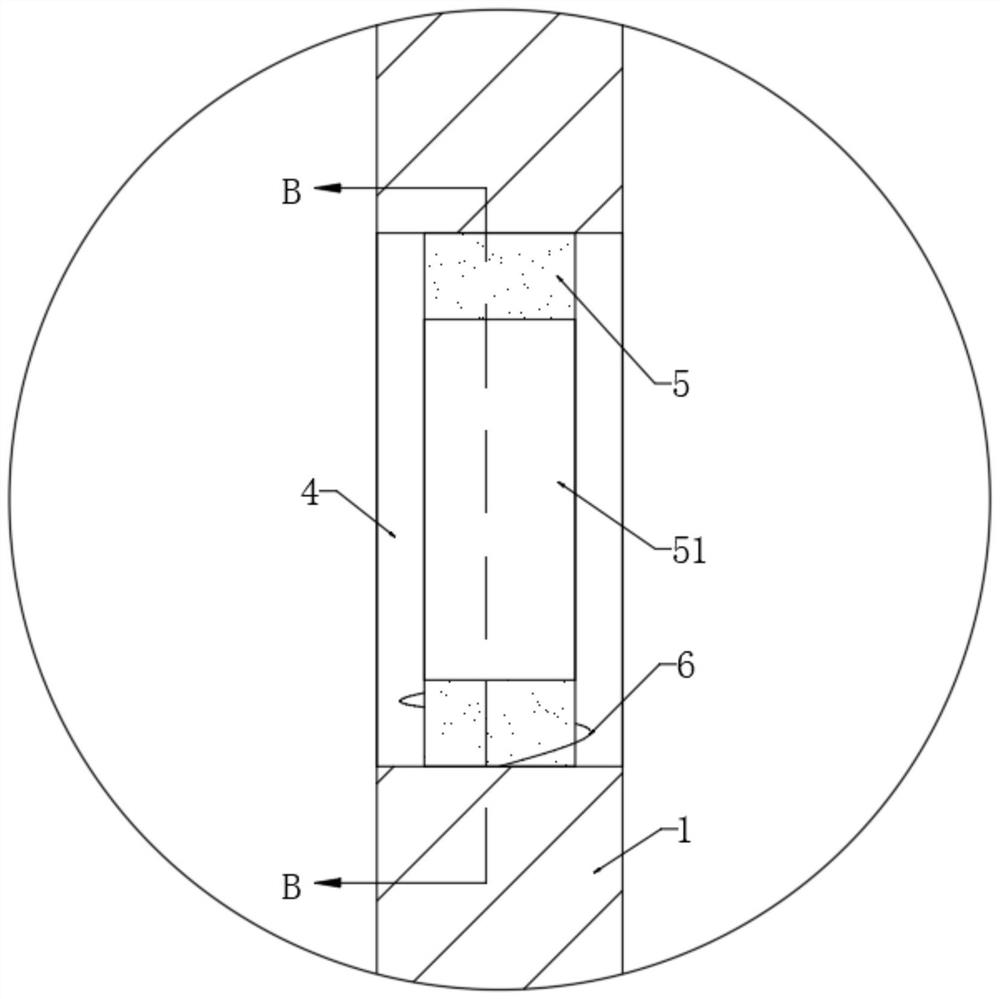
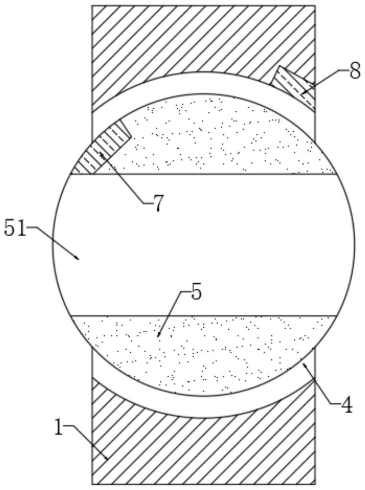
[0022] refer to Figure 1-5 , an outdoor rainproof power cabinet, comprising a cabinet body 1, the side wall of the cabinet body 1 is provided with a plurality of cylindrical holes 4, the side wall of the cabinet body 1 is provided with an air groove 2, and the cylindrical hole 4 is sealed and rotated to be connected with a sealing Column 5, the side wall of sealing column 5 is provided with heat dissipation hole 51, and the aperture of cylinder hole 4 is larger, and the aperture of heat dissipation hole 51 is smaller than the aperture of heat dissipation hole 51, to ensure that between sealing column 5 and cylinder hole 4 there is good air tightness. The side wall of the sealing column 5 is embedded with a first iron sheet 7, the cylindrical hole 4 is embedded with an electromagnet 8, and a power supply device for supplying power to the electromagnet 8 is installed in the air groove 2, and the sealing column 5 is connected in rotation by a torsion spring 6. In the cylindrica...

Embodiment 2

[0028] refer to Figure 6 , different from Embodiment 1, the inner top of the air tank 2 is provided with a plurality of closed coils 12, and the inner top of the cabinet body 1 is fixedly connected with a pump liquid cylinder 13. Specifically, the pump liquid cylinder 13 is made of a rubber material with good elasticity. As a result, the pump liquid cylinder 13 can have good deformability. And the side wall of the pump liquid cylinder 13 is fixedly connected with the second iron sheet 14, and the side wall of the cabinet body 1 is provided with a liquid storage tank 17, and a one-way liquid inlet pipe 15 is connected between the liquid storage tank 17 and the pump liquid cylinder 13 respectively. Along with the one-way liquid return pipe 16 , an air hole 171 is opened on the side wall of the liquid storage tank 17 .

[0029] By providing the air holes 171 , cooling liquid can be added to the liquid storage tank 17 through the air holes 171 , and at the same time, the cooling...


PUM


Abstract

The invention discloses an outdoor rainproof electric power cabinet. The cabinet comprises a cabinet body, wherein a plurality of cylindrical holes are formed in a side wall of the cabinet body, an air groove is formed in the side wall of the cabinet body, a sealing column is rotatably connected into a cylindrical hole in a sealed mode, a heat dissipation hole is formed in a side wall of the sealing column, a first iron sheet is embedded into a side wall of the sealing column, an electromagnet is embedded into the cylindrical hole, a power supply device for supplying power to the electromagnetis installed in the air groove, and the sealing column is rotatably connected into the cylindrical hole through a torsional spring. The cabinet is advantaged in that the electromagnet is powered on through the power supply device to enable the sealing column to rotate, the cylindrical hole can be blocked to prevent rainwater from entering the cabinet body, in the absence of rain, the electromagnet is powered off, and the sealing column opens the cylindrical hole under the action of the torsional spring, so air inside and outside the power cabinet can interact, and the heat dissipation performance of the power cabinet is guaranteed.

Description

technical field [0001] The invention relates to the related technical field of power cabinets, in particular to an outdoor rainproof power cabinet. Background technique [0002] For outdoor power cabinets, in order to cope with the harsh outdoor weather, good rainproof and heat dissipation functions are required. Especially in windy and windy weather, the horizontal airflow easily entrains rainwater into the power cabinet. For this reason, rainproof covers are often installed at the cooling holes of the power cabinet to block rainwater, but also block the interaction of air inside and outside the power cabinet. As a result, the heat dissipation performance of the power cabinet is poor. Accordingly, this application document proposes an outdoor rainproof power cabinet. Contents of the invention [0003] The purpose of the present invention is to solve the shortcomings in the prior art, and propose an outdoor rainproof power cabinet. [0004] In order to achieve the above...

Claims


Application Information

Patent Timeline
Patent Type & Authority Applications(China)
IPC IPC(8): H02B1/28H02B1/56H02N2/18H02K7/18H02B1/30F04B43/08F03D9/25
CPCF04B43/08F03D9/25H02B1/28H02B1/306H02B1/565H02K7/183H02K7/1846H02N2/186Y02E10/72Y02A30/14
Inventor 窦晨阳
Owner 牡丹江鸿鑫设备制造有限公司
Learn More