
Intelligent power module

A technology of intelligent power modules and diodes, which is applied in the direction of output power conversion device, conversion of AC power input to AC power output, conversion of AC power input to DC power output, etc., which can solve the problems of increasing process difficulty and cost, large PFC current, Difficulties in structural design and other issues

Pending Publication Date: 2020-10-23
广东汇芯半导体有限公司
View PDF0 Cites 0 Cited by
  • Summary
  • Abstract
  • Description
  • Claims
  • Application Information

AI Technical Summary

Problems solved by technology

Switching at high currents can also cause serious electromagnetic interference, causing EMI problems
In addition, the volume and weight of the external inductor need to be large, and it cannot be directly soldered on the PCB, which brings great difficulties to the structural design.
For the PFC and inverter two-in-one modules currently on the market, due to the large current that the PFC part bears, it causes serious local heating.
In order to improve heat dissipation, it is also necessary to add a heat sink under the PFC wafer, which increases the difficulty and cost of the process

Method used


Image

  • Intelligent power module
  • Intelligent power module
  • Intelligent power module

Examples


Embodiment

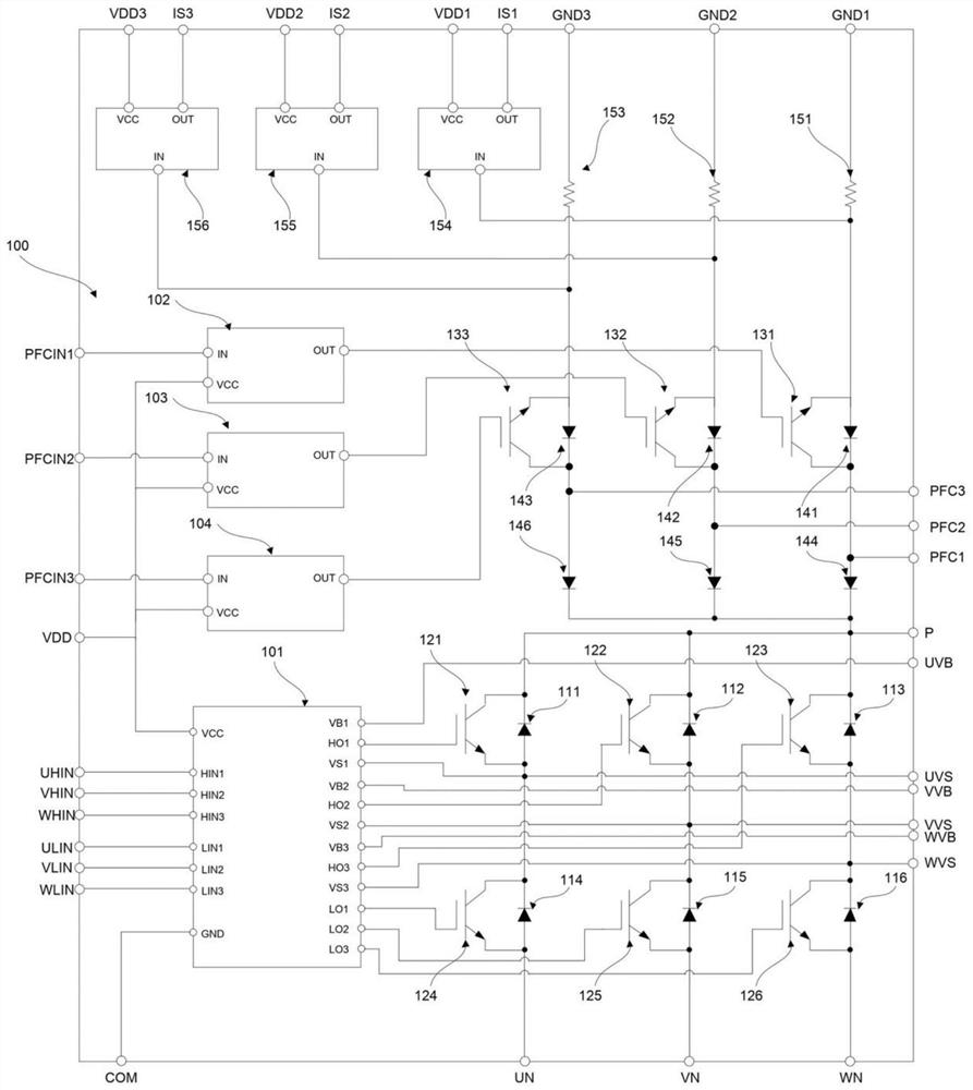
[0018] see figure 2, the present invention proposes an intelligent power module 100, including a HVIC (High Voltage Integrated Circuit, high-voltage integrated circuit) tube 101, a three-phase bridge inverter circuit, a first drive IC tube 102, a second drive IC tube 103, a third drive IC tube 103, and a third drive IC tube 103. IC tube 104, first switch tube 131, second switch tube 132, third switch tube 133, first diode 141, second diode 142, third diode 143, fourth diode 144, The fifth diode 145, the sixth diode 146, the first detection resistor 151, the second detection resistor 152, the third detection resistor 153, the first comparator 154, the second comparator 155 and the third comparator 156; The HVIC tube is connected to the three-phase bridge inverter circuit for receiving external control signals and controlling each switching device of the three-phase bridge inverter circuit to complete the inversion; A PFC control input terminal PFCIN1, the output terminal of t...


PUM


Abstract

The invention discloses an intelligent power module which comprises an HVIC tube, a three-phase bridge inverter circuit, a switching tube, a diode, a detection resistor and a comparator. The HVIC tubeis connected with the three-phase bridge type inverter circuit and is used for receiving an external control signal and controlling each switching device of the three-phase bridge type inverter circuit to finish inversion; external alternating current is rectified into direct current; the three boost unit circuits are connected in parallel, respectively input into the intelligent power module through three inductors connected in parallel, respectively form three boost unit circuits connected in parallel with a switching tube and a diode in the module, detect the current of a PFC circuit through three detection resistors, output the current to the outside through a comparator, and externally control the three boost unit circuits to work. The staggered PFC circuit and the inverter circuit are integrated, current ripples are reduced, local heating of the module is reduced, integrated packaging is adopted, the cost of independent packaging is saved, and the reliability is improved.

Description

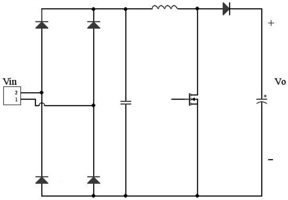
technical field [0001] The invention relates to the technical field of power semiconductors, in particular to an intelligent power module. Background technique [0002] In most home appliance applications, the mains power needs to be converted into DC power through a rectifier bridge and a PFC (Power Factor Correction) circuit. At present, the PFC in home appliances such as air conditioners adopts the boost circuit form, such as figure 1 Shown: Insert a boost circuit between the rectifier bridge and the large electrolytic capacitor, force the current to follow the voltage change, and keep the two in the same phase, there is no obvious waveform distortion, so that the power factor of the circuit is close to 1. From the working principle of the boost circuit, it can be seen that the current of the inductor works in a continuous mode and can be modulated in the entire power frequency cycle, so the circuit can achieve a relatively high power factor. Compared with other circuit...

Claims


Application Information

Patent Timeline
IPC IPC(8): H02M1/42H02M5/458H02M7/5387H02M1/12H02P27/08
CPCH02M1/42H02M1/4225H02M5/4585H02M7/5387H02M7/53873H02M1/12H02P27/08Y02B70/10
Inventor 冯锴雄杨忠添
Owner 广东汇芯半导体有限公司
Learn More