
Interbody fusion cage

An intervertebral fusion device and fusion device technology, applied in the field of intervertebral fusion devices, can solve problems such as vertebral body collapse, long operation time, and many steps

Pending Publication Date: 2020-10-27
广州民鋆医疗科技发展有限公司
View PDF0 Cites 0 Cited by
  • Summary
  • Abstract
  • Description
  • Claims
  • Application Information

AI Technical Summary

Problems solved by technology

[0003] At present, the intervertebral fusion devices on the market are mainly divided into three types in terms of use. The first type is used in conjunction with internal fixation screws. As the operator, the doctor takes a long time to operate and has a heavy workload. The cost of surgery and consumables for both intervertebral fusion cages; the second is expandable intervertebral fusion cages. Most expandable intervertebral fusion cages are made of titanium alloy. The fusion cage exits the intervertebral disc, and the titanium alloy fusion cage is harder than the vertebral body, which is likely to cause the collapse of the vertebral body. As the patient ages, the ligaments and muscles become soft, and the effect of preventing tooth regression will also weaken, leading to the risk of prolapse; The three types are fusion cages with inserts or screws. For patients with loose bones, the fixation of inserts and screws is not reliable, and the implantation of fusion cages, inserts, and screws needs to be divided into multiple implants. Many steps, difficult to use

Method used


Image

  • Interbody fusion cage
  • Interbody fusion cage
  • Interbody fusion cage

Examples


Embodiment Construction

[0026] This part will describe the specific embodiment of the present invention in detail, and the preferred embodiment of the present invention is shown in the accompanying drawings. Each technical feature and overall technical solution of the invention, but it should not be understood as a limitation on the protection scope of the present invention.

[0027] In the present invention, if there is a description of directions (up, down, left, right, front and back), it is only for the convenience of describing the technical solution of the present invention, rather than indicating or implying that the referred technical features must have specific Orientation, construction and operation in a particular orientation, therefore should not be construed as limiting the invention.

[0028] In the present invention, "several" means one or more, "multiple" means more than two, "greater than", "less than", "exceeding", etc. are understood as excluding the original number; "above", "belo...


PUM


Abstract

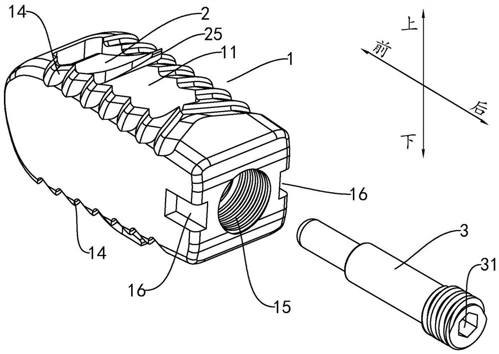
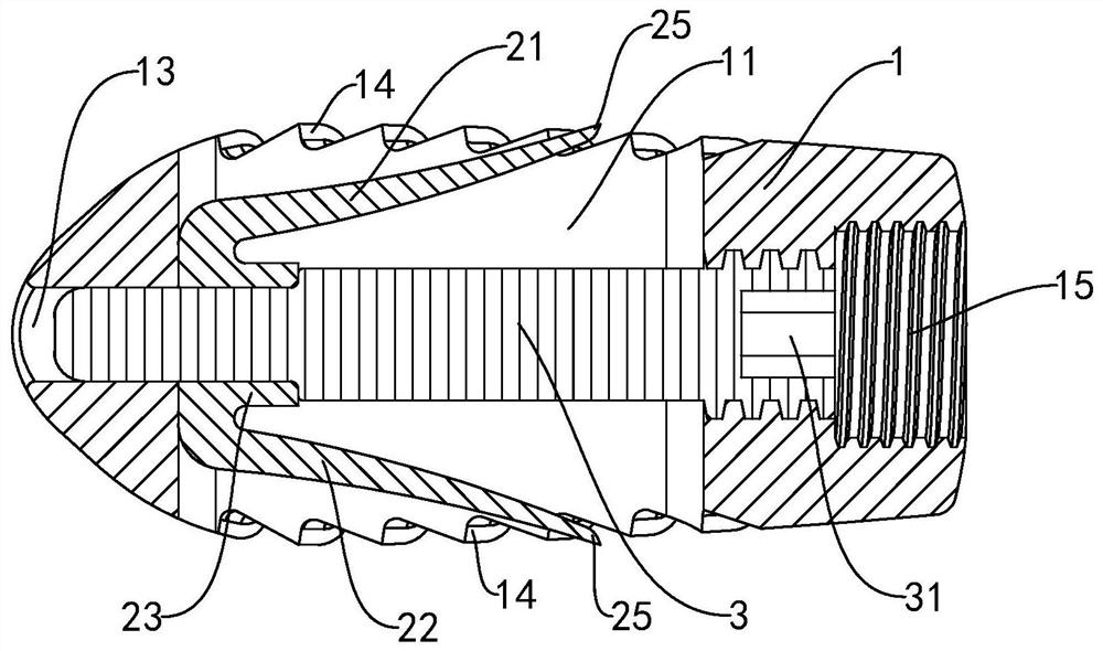
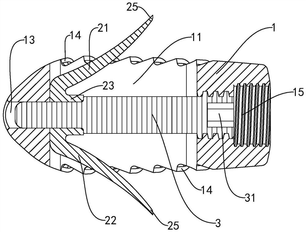
The invention discloses an interbody fusion cage. The interbody fusion cage comprises a fusion cage body, a limiting part and a connecting part, wherein the fusion cage body is provided with a bone grafting cavity; the bone grafting cavity communicates with the outside in the vertical direction; the connecting part is used for fixing the limiting part in the bone grafting cavity; the limiting partis provided with a first locking plate and a second locking plate; the limiting part can deform; the first locking plate can extend upwards out of the bone grafting cavity; and the second locking plate can extend downwards out of the bone grafting cavity. According to the interbody fusion cage, the limiting part can penetrate into the upper vertebral body and the lower vertebral body only by inserting the interbody fusion cage into the interbody once, so that surgical operation steps can be reduced, and operation is easy and convenient; the problem that the interbody fusion cage is withdrawnfrom the intervertebral disc can be effectively improved through the arrangement of the limiting part; and the interbody fusion cage has the anti-retreating function, so that the surgical risk of a patient is reduced.

Description

technical field [0001] The invention is used in the field of medical instruments, and in particular relates to an intervertebral fusion device. Background technique [0002] Intervertebral bone graft fusion is to connect or fuse two or more adjacent vertebrae to achieve the purpose of rebuilding the stability of the spine. This fusion procedure usually involves the placement of an intervertebral cage filled with bone tissue or artificial bone within the discs of two adjacent vertebrae so that they "fused" together instead of being completely removed during surgery. / Partial resection of the nucleus pulposus and cartilage tissue in the intervertebral disc. [0003] At present, the intervertebral fusion devices on the market are mainly divided into three types in terms of use. The first type is used in conjunction with internal fixation screws. As the operator, the doctor takes a long time to operate and has a heavy workload. The cost of surgery and consumables for both int...

Claims


Application Information

Patent Timeline
IPC IPC(8): A61F2/44
CPCA61F2/4455
Inventor 黎庆初申维波
Owner 广州民鋆医疗科技发展有限公司
Learn More