Sandstone screening machine for transportation construction
A technology for screening machines and sand and gravel, which is applied in separation methods, chemical instruments and methods, and filtration and screening, and can solve problems such as insufficient screening, poor screening effect, and increased equipment load.
- Summary
- Abstract
- Description
- Claims
- Application Information
AI Technical Summary
Problems solved by technology
Method used
Image
Examples
Embodiment 1
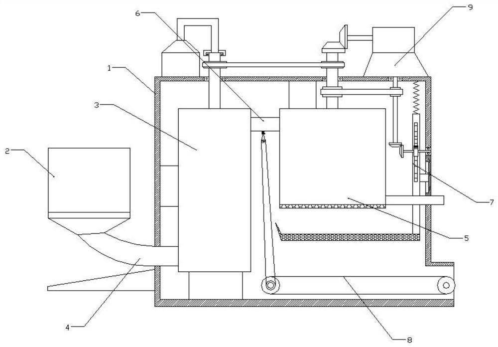
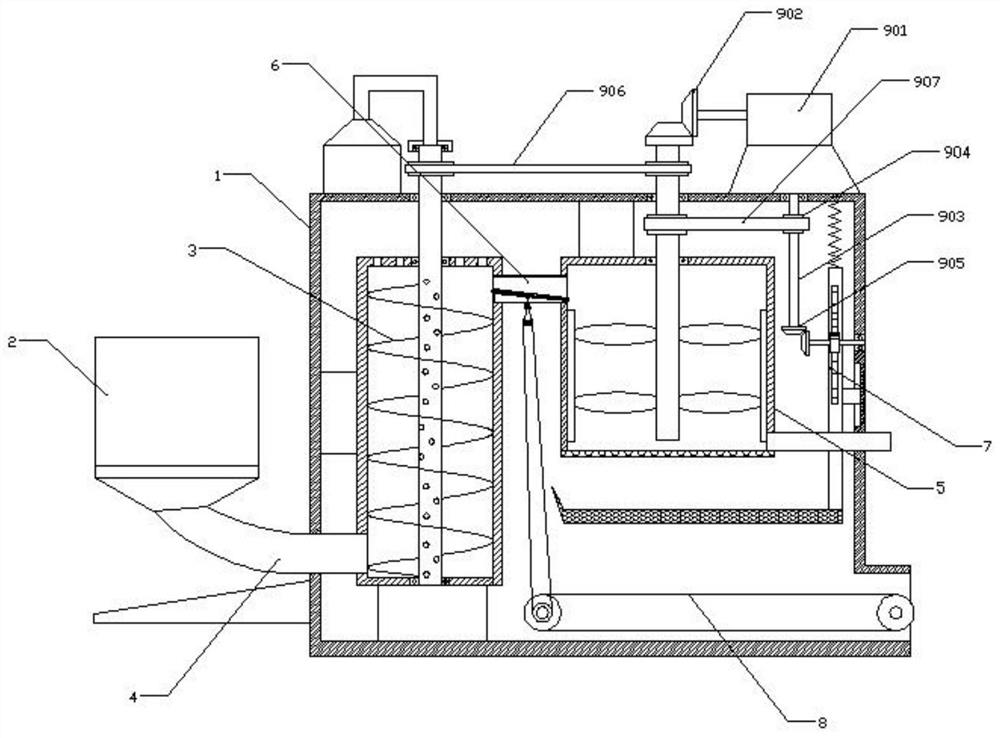
[0041] This embodiment is a sand and gravel screening machine for traffic construction, comprising a frame 1, a feeding cylinder 2 is provided on the left side of the frame 1, a material lifting assembly 3 is provided on the left side of the inner cavity of the frame 2, and the feeding cylinder 2 There is a material guide assembly 4 connected between the lower end and the left side wall of the material lifting assembly 3, a stirring assembly 5 is provided on the right side of the inner cavity of the frame 1, and a square pipe 6 is connected between the stirring assembly 5 and the upper end of the material lifting assembly 3, The right side wall of the inner chamber of the frame 1 is connected with a sieve assembly 7 , a discharge assembly 8 is arranged below the sieve assembly 7 , and a first transmission assembly 9 is connected with the top of the frame 1 .
[0042] The concrete steps of using the gravel screening machine for traffic construction are as follows:
[0043] S1. ...
Embodiment 2
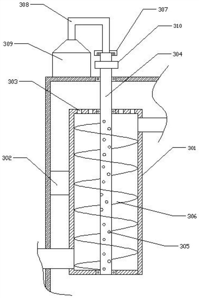
[0049] On the basis of Embodiment 1, the material lifting assembly 3 includes a feeding housing 301, a fixing seat 302 is connected between the feeding housing 301 and the inner wall of the frame 1, and an exhaust port 303 is opened on the top of the feeding housing 301, and the feeding housing The inner cavity of the body 301 is rotatably connected with a hollow shaft 304, and several groups of air outlet holes 305 are evenly distributed on the hollow shaft 304. The outer wall of the hollow shaft 304 is connected with a screw conveying blade 306, and the upper end of the hollow shaft 304 is rotatably connected with a pressing block 307. The top of block 307 is connected with air intake pipe 308, and the other end of air intake pipe 308 is connected with hot air blower 309, and hot air blower 309 is affixed to frame 1, and the outer wall top of hollow shaft 304 is connected with first pulley 310.
[0050] The material guide assembly 4 includes a material guide hopper 401, the u...
Embodiment 3
[0057] On the basis of Embodiment 2, the inner cavity of the square tube 6 is provided with a guide swash plate 601, the left end of the guide swash plate 601 is hinged to the inner wall of the square tube 6 through a pin shaft, the right end of the guide swash plate 601 is inclined downward, and the guide swash plate The bottom of 601 is fitted with top block 602, and the bottom of top block 602 is connected with support bar 603, and the lower end of support bar 603 stretches out square tube 6 and is connected with stopper 604, and the bottom of stop block 604 and square tube 6 is connected with reducer. The vibration spring 605, the bottom of the block 604 is attached with a cam 606, the rear end of the cam 606 is connected with a rotating shaft 607, and the outer wall of the rotating shaft 607 is connected with a driven sprocket 608.
[0058] The discharge assembly 8 includes two sets of conveying rollers 801 arranged in parallel. A conveying belt 802 is set between the oute...
PUM
 Abstract
Description
Claims
Application Information
 - R&D
- Intellectual Property
- Life Sciences
- Materials
- Tech Scout
- Unparalleled Data Quality
- Higher Quality Content
- 60% Fewer Hallucinations
Browse by: Latest US Patents, China's latest patents, Technical Efficacy Thesaurus, Application Domain, Technology Topic, Popular Technical Reports.
© 2025 PatSnap. All rights reserved.Legal|Privacy policy|Modern Slavery Act Transparency Statement|Sitemap|About US| Contact US: help@patsnap.com


