
Powder storage tank

A technology for storage tanks and powders, applied in the direction of loading/unloading, containers, packaging, etc., which can solve the problems of general arch breaking effect, loud noise, and poor fluidity of the pneumatic vibrator 12, and achieve ingenious and economical installation positions and installation methods High efficiency and good arch breaking effect

Pending Publication Date: 2020-10-27
上海富昶环保科技有限公司
View PDF0 Cites 1 Cited by
  • Summary
  • Abstract
  • Description
  • Claims
  • Application Information

AI Technical Summary

Problems solved by technology

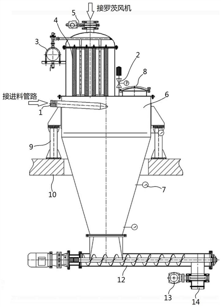
[0003] It can be seen that the above-mentioned traditional powder storage tank is loaded and stored through negative pressure transportation. This device only stores and transports some materials that have good fluidity and are not easy to absorb moisture and agglomerate. For general fluidity and easy to absorb The storage of wet and agglomerated materials is prone to bridging phenomenon. The bottom material is evacuated, and the upper material bridging will no longer fall, so normal transportation cannot be realized.
[0004] In order to solve this problem in the traditional way, a pneumatic oscillator 12 is generally installed on the surface of the tank body 6, but there are many disadvantages in this way, one of which is that it will generate very large noise, form noise pollution, and affect the physical and mental health of nearby personnel; The 2nd, can cause damage to the junction of support leg 9 and platform 10, make bolt loose, the bolt hole wall crack on the platform; For heavily agglomerated materials, the effect is very small

Method used


Image

  • Powder storage tank
  • Powder storage tank
  • Powder storage tank

Examples


Embodiment Construction

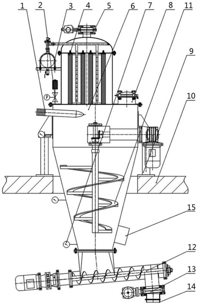
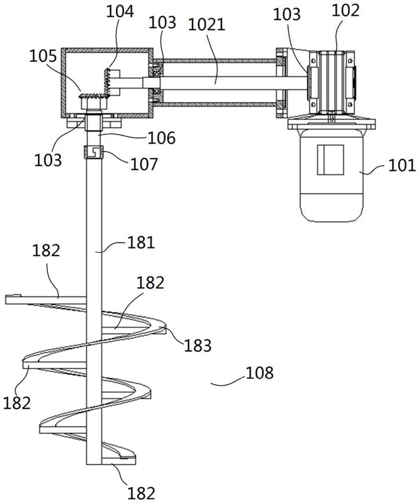
[0022] A specific embodiment of a powder storage tank of the present invention, such as Figure 2-Figure 3 As shown, the powder storage tank includes a tank body 6 with a conical bottom, and a feed pipe 1 is arranged on the top of the tank body 6, and the feed pipe 1 is welded on the top of the tank body 6. The tank body 6 has a top cover, and the top cover is provided with a There are respirator 2, reverse blowing air bag assembly 3, gas material separator 4 and suction port, the suction port is provided with a pneumatic butterfly valve, the lower end of the tank body 6 is provided with a screw conveyor 12, and the screw conveyor 12 is self-contained from the feed end It is arranged inclined upward towards the discharge end, and the tank body 6 is provided with an arch breaking mechanism 11, which includes a drive motor 101, a reduction box 102 (with a reduction mechanism inside), and a bearing box (with a bearing 103 inside) that are sequentially connected by transmission. ,...


PUM


Abstract

The invention relates to a powder storage tank. The powder storage tank comprises a tank body; the lower part of the tank body is conical; a feeding pipe is arranged at the upper part of the tank body; the tank body is provided with an upper cover; a respirator, a blowback air pocket component, an air and material separator and an air suction port are arranged on the upper cover; a screw conveyeris arranged at the lower end of the tank body; an arch breaking mechanism is arranged on the tank body and comprises a drive motor, a reduction gearbox, a bevel gear set, a transmission shaft and a stirrer in drive joint sequentially; the bevel gear set comprises a driving bevel gear and a driven bevel gear; the driving bevel gear is mounted at the outer end of a horizontally arranged output shaftof the reduction gearbox; the driven bevel gear is mounted at the upper end of the transmission shaft; the drive motor and the reduction gearbox are mounted at the external part of the tank body; theoutput shaft of the reduction gearbox penetrates through the tank body and is in rotary seal fit with the tank body; the stirrer comprises a stirring paddle, and the axis of the stirring paddle is vertically arranged; the stirring paddle is positioned a conical structure at the lower part of the tank body; and the lowest end of the stirring paddle extends to the conical opening of the conical structure. The powder storage tank is small in noise, high in arch breaking capacity and is suitable for material with poor fluidity and likely to absorb moisture for caking.

Description

technical field [0001] The invention relates to a powder storage tank. Background technique [0002] Powder storage tanks are often used in food, pharmaceutical, wine, beverage, dye and chemical industries. For example attached figure 1 Shown is a traditional powder storage tank, which includes a tank body 6, a feed pipe 1 fixed on the tank body 6, a respirator 2 with a pneumatic valve, a blowback air bag assembly 3, and a gas-material separation tank are installed on the upper cover. device 4, air suction port pneumatic butterfly valve 5, maintenance manhole 8 and material level gauge 7, tank body 6 is fixed on platform 10 through outrigger 9, screw conveyor 12 is provided at the lower end of tank body 6, and the exit of screw conveyor 12 The feed port is equipped with a pneumatic butterfly valve 13 and a feed port 14. The screw conveyor 12 is composed of a motor, a reducer, a bearing box, a screw conveying shaft, a feed pipe, an oil seal, a bearing with a seat, and a con...

Claims


Application Information

Patent Timeline
Patent Type & Authority Applications(China)
IPC IPC(8): B65D88/68B65D88/64B65G65/46
CPCB65D88/68B65D88/64B65G65/46
Inventor 吴启虎刘利强牛伟牛寅
Owner 上海富昶环保科技有限公司
Learn More