Single crystal furnace shutdown thermal field damage prevention method

A single crystal furnace and thermal field technology, applied in the direction of single crystal growth, single crystal growth, chemical instruments and methods, etc., can solve the problems of container and support container damage, liquid silicon volume expansion, difficult stress, etc., to slow down silicon condensation speed, reduce stress concentration, and accelerate the effect of coagulation

Pending Publication Date: 2020-10-27
JA XINGTAI SOLAR CO LTD
View PDF4 Cites 0 Cited by
  • Summary
  • Abstract
  • Description
  • Claims
  • Application Information

AI Technical Summary

Problems solved by technology

[0002] During unconventional shutdown, liquid silicon will expand in volume during solidification and cooling, and the crystallization sequence of liquid silicon is that the liquid surface first forms a crystallization surface, and the crystallization surface will extend downward as the temperature decreases, but close to the middle and bottom of the liquid silicon Since the upper crystallization forms an insulating layer, the liquid silicon at the middle bottom and the upper crystallization surface form a large temperature gradient. This change will form a stress that is difficult to release from the upper part under the inverse ratio curve of temperature and time.
[0003] The volume change of liquid silicon will look for weak points around the quartz crucible, but this volume change is often restricted by the quartz crucible and the crucible state supporting the quartz crucible and cannot proceed freely, so internal stress is generated, and the stress changes with the outside world. Slow contact at normal temperature reaches the highest level, making the container and supporting container unable to withstand damage

Method used


Image

  • Single crystal furnace shutdown thermal field damage prevention method
  • Single crystal furnace shutdown thermal field damage prevention method

Examples


Embodiment Construction

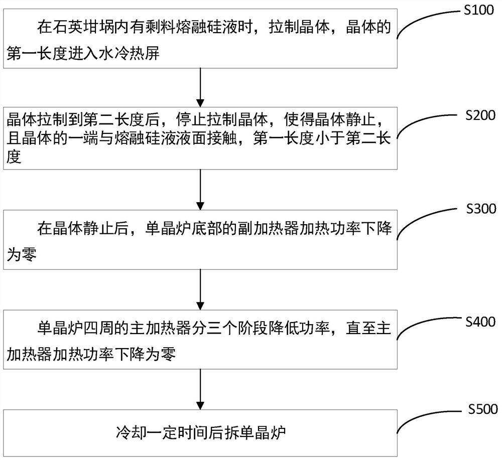
[0033] The method for stopping the single crystal furnace to prevent thermal field damage according to the embodiment of the first aspect of the present invention will be described in detail below with reference to the accompanying drawings.

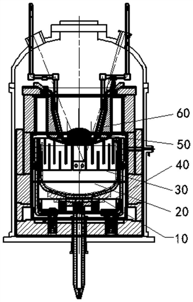
[0034] In order to facilitate the understanding of the method for stopping the single crystal furnace to prevent thermal field damage in this application, the structure of the single crystal furnace is first described, as figure 2 As shown, the single crystal furnace includes: a quartz crucible 10 for containing molten silicon liquid 20, a water-cooled heat shield 60 arranged above the quartz crucible 10, an auxiliary heater 40 arranged at the bottom of the single crystal furnace, and a 10 around and located at the main heater 30 below the water-cooled heat shield 60.

[0035] Combine below figure 1 and figure 2 , to describe in detail the method of stopping the single crystal furnace to prevent thermal field damage in the embodiment...


PUM


Abstract

The invention provides a single crystal furnace shutdown thermal field damage prevention method which comprises the following steps of: 1, drawing a crystal when residual molten silicon liquid existsin a quartz crucible, and enabling the first length of the crystal to enter a water-cooling heat shield; 2, after the crystal is drawn to a second length, stopping drawing the crystal, and enabling one end of the crystal to be in contact with the liquid level of the molten silicon liquid; 3, after the crystal is static, reducing the heating power of an auxiliary heater at the bottom of the singlecrystal furnace to zero; 4, reducing the power of the main heaters around the single crystal furnace in three stages until the heating power of the main heaters is reduced to zero; and 5, cooling fora certain period of time, and disassembling the single crystal furnace. According to the method, a single crystal with a certain length can be drawn to increase the heat transfer volume, accelerate the condensation speed of molten silicon liquid in the middle of a quartz crucible and reduce the stress concentration ratio, a heater on the single crystal furnace stops heating in a stepped mode, thecondensation speed of silicon around the quartz crucible is reduced, a stress release area is reserved, and therefore the integrity of a thermal field is guaranteed to the maximum extent.

Description

technical field [0001] The invention mainly relates to the technical field of crystal material processing equipment, and in particular to a method for stopping a single crystal furnace to prevent thermal field damage. Background technique [0002] During unconventional shutdown, liquid silicon will expand in volume during solidification and cooling, and the crystallization sequence of liquid silicon is that the liquid surface first forms a crystallization surface, and the crystallization surface will extend downward as the temperature decreases, but close to the middle and bottom of the liquid silicon Since the upper part crystallizes to form an insulating layer, the liquid silicon at the middle bottom and the upper crystallization surface form a large temperature gradient. This change will form stress that is difficult to release from the upper part under the inverse ratio curve of temperature and time. [0003] The volume change of liquid silicon will look for weak points ...

Claims


Application Information

Patent Timeline
IPC IPC(8): C30B15/00C30B28/10C30B29/06
CPCC30B15/00C30B28/10C30B29/06
Inventor 赵贝李增卫赵群
Owner JA XINGTAI SOLAR CO LTD
Why Eureka
Try Eureka