
Slope reinforcing retaining wall and construction method thereof

A technology for retaining walls and slopes, which is applied in the field of geotechnical engineering, and can solve problems such as failure of reinforced slopes, economic waste, and large rainwater scouring area on the surface of the retaining wall at an inclined angle

Active Publication Date: 2020-10-27
CHINA CONSTR FIFTH ENG DIV CORP LTD
View PDF6 Cites 3 Cited by
  • Summary
  • Abstract
  • Description
  • Claims
  • Application Information

AI Technical Summary

Problems solved by technology

[0003] Due to the small section width of the conventional rigid gravity retaining wall, the anti-sliding friction resistance generated at the bottom is not enough, resulting in the overall sliding or toppling failure of the retaining wall, which makes the reinforced slope invalid. In addition, the cost is expensive, and there are no requirements for the grade of the slope High engineering has caused economic waste; flexible gravity retaining walls such as conventional geogrid reinforcement often cause overall instability and damage to the foundation at the bottom due to water softening. The section width of the wall is relatively large, so it occupies a relatively wide site, and the inclination angle of the retaining wall is relatively slow, so that the surface of the retaining wall is subject to a large area of ​​rainwater erosion, which is prone to shallow collapse and damage of the retaining wall. The design site for slope reinforcement is limited and the perennial rainfall frequency The big southern region is obviously not suitable

Method used


Image

  • Slope reinforcing retaining wall and construction method thereof

Examples


Embodiment Construction

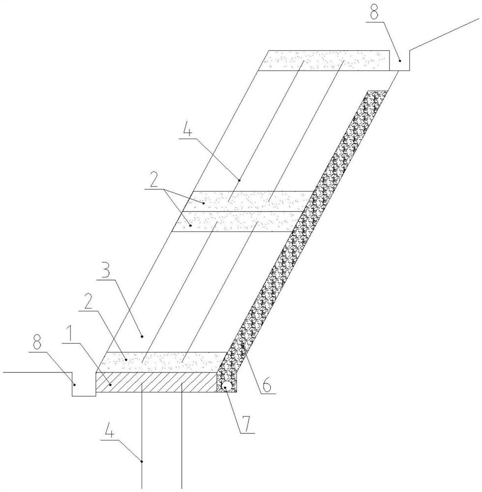
[0026] Such as figure 1 As shown, the slope reinforced retaining wall structure disclosed in the present invention includes a unit structure layer formed by a concrete cushion layer 1 and a cement soil layer 2 above it sandwiching a backfill layer 3 . The unit structure layer can be set in multiple layers according to actual needs, and the inclination angle of each unit structure layer is consistent with the slope of the slope. The concrete cushion 1 is provided with several hollow steel pipes 4 vertically pressed downward into the soil, so that the concrete cushion 1 and the hollow steel pipes 4 are combined to form a rigid cushion. The unit structure layer is provided with hollow steel pipes 4 with the same inclination angle, and the two ends of the hollow steel pipes 4 are respectively restrained and fixed by the cement soil layer 2, so that the unit structure layer forms a stable structure.

[0027] Hollow steel pipes 3 are arranged in multiple rows along the longitudinal...


PUM


Abstract

The invention discloses a slope reinforcing retaining wall and a construction method thereof. The retaining wall comprises a concrete cushion and a plurality of unit structural layers formed by a backfill soil layer entraining a concrete soil layer above the concrete cushion. The inclination angle of each unit structural layer is consistent with the grade of the slope. A plurality of hollow steelpipes vertically pressed unto a soil body downward are arranged on the concrete cushion. The hollow steel pipes of same inclination angle are arranged in the unit structural layers. Two ends of the hollow steel pipes are restrained and fixed by concrete soil layers. A base structure of the retaining wall is relatively high in bearing capacity and unlikely to soften and permeate. The unit structural layers are stable structural bodies and have the characteristics of isolating water and being unlikely to soften. The inclination angle of the retaining wall can be arranged relatively steeply, so that the cost of filling engineering is saved. A soil material of the retaining wall is fully taken from an excavated natural soil body, so that the engineering cost can be saved. The slope reinforcingretaining wall is particularly suitable for south region with limited sites for reinforced design of the slope and high perennial rainfall frequency.

Description

technical field [0001] The invention belongs to the field of geotechnical engineering, in particular to a slope reinforced retaining wall and a construction method thereof. Background technique [0002] In the slope treatment process, excavated soil materials and reinforcement materials are often used to combine them through different design schemes and construction methods to form a flexible reinforced soil retaining wall. This method is economical Cost, simple construction, fast construction speed and other advantages. At present, the most reinforced material in reinforced soil is mainly geogrid among synthetic reinforced materials. [0003] Due to the small section width of the conventional rigid gravity retaining wall, the anti-sliding friction resistance generated at the bottom is not enough, resulting in the overall sliding or toppling failure of the retaining wall, which makes the reinforced slope invalid. In addition, the cost is expensive, and there are no requirem...

Claims


Application Information

Patent Timeline
Patent Type & Authority Applications(China)
IPC IPC(8): E02D17/20E02D29/02
CPCE02D17/20E02D29/02E02D29/0241E02D2300/002E02D2300/0029E02D2300/0045
Inventor 陈海雄姚木左欢肖湘明王涛于学浩
Owner CHINA CONSTR FIFTH ENG DIV CORP LTD
Learn More