Automatic grout spraying facility for laying wet masonry stone retaining wall

A technology for equipment installation and stone barriers, which is applied in construction and building construction, etc., can solve the problems of increasing work difficulty and workload, higher requirements for experience and physical strength, and greater difficulty in equipment maintenance, so as to reduce maintenance costs and reduce costs. Difficulty, ensure work efficiency, and reduce the effect of production costs

Inactive Publication Date: 2020-10-27
NORTH CHINA UNIV OF WATER RESOURCES & ELECTRIC POWER
View PDF5 Cites 0 Cited by
  • Summary
  • Abstract
  • Description
  • Claims
  • Application Information

AI Technical Summary

Problems solved by technology

[0002] In construction engineering, it is often necessary to build a masonry retaining wall, and the masonry retaining wall needs to be sprayed after the masonry building is formed. The traditional spraying method is to spray the masonry with manual hand-held spraying equipment. The stone retaining wall is sprayed. In order to ensure the uniform effect of spraying, it is necessary to move the nozzle at a constant speed and slowly. Therefore, the experience and physical strength of the staff are relatively high during the spraying process, which increases the difficulty and difficulty of the work for the staff holding the nozzle. workload
[0003] In order to solve the above problems, those skilled in the art have designed more automatic spraying equipment, although these automatic spraying equipment do not need the staff to hold the nozzle to spray, which improves the work efficiency and ensures the quality of work, but these automatic spraying equipment, the general structure is relatively Complicated, high production cost, difficult to maintain the device during use

Method used


Image

  • Automatic grout spraying facility for laying wet masonry stone retaining wall
  • Automatic grout spraying facility for laying wet masonry stone retaining wall
  • Automatic grout spraying facility for laying wet masonry stone retaining wall

Examples


Embodiment Construction

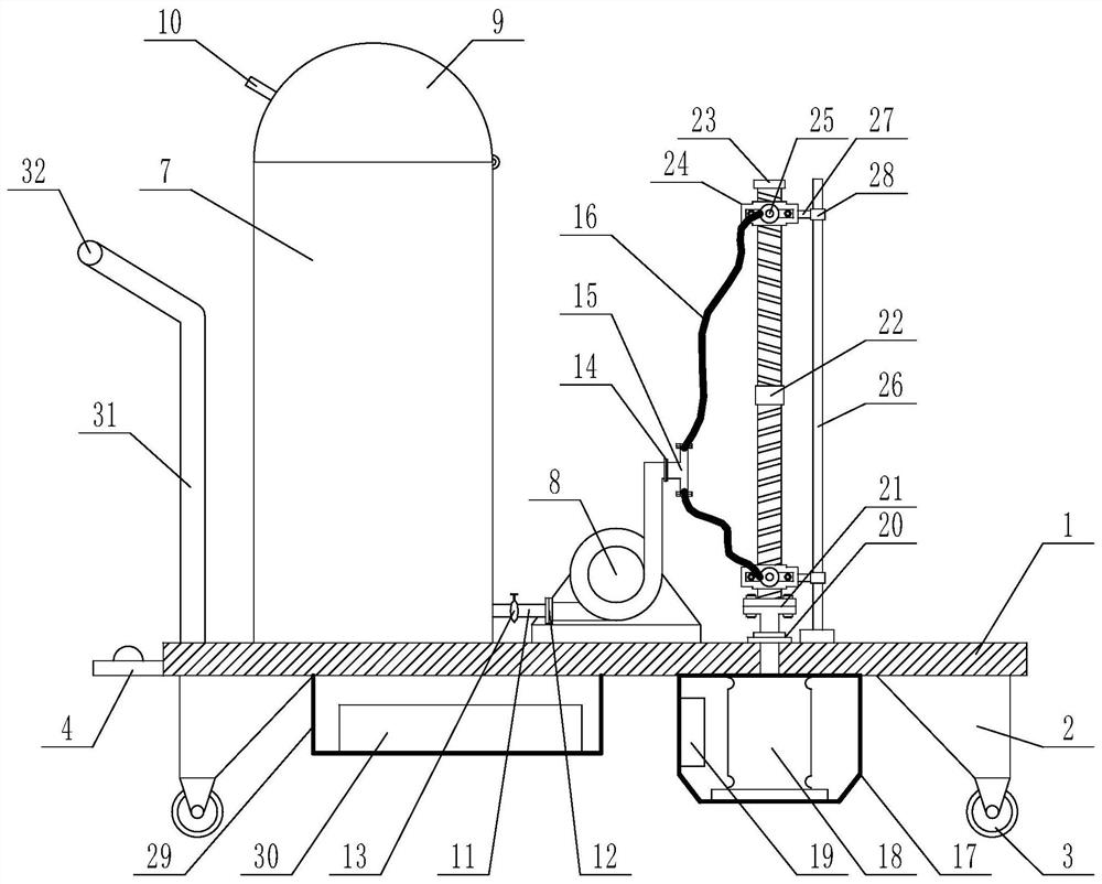
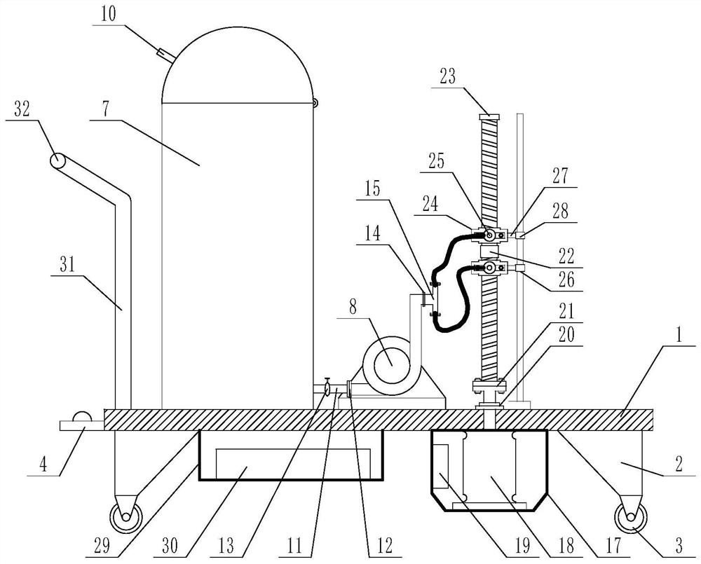
[0027] The present invention is specifically described below in conjunction with accompanying drawing, as figure 1 As shown in -4, the inventive point of the present application is to fix the mounting bracket 2 at the four corners of the lower surface of the mounting plate, the universal wheel 3 is installed at the lower end of the bracket, and the handrail and the pedal 4 are fixedly installed on one side of the mounting plate. The pedal is provided with a spray pump foot switch 5 and a servo motor foot switch 6, and a paint storage tank 7 and a spray pump 8 are fixedly installed on the surface of the mounting plate, and the paint storage tank is a cylindrical tank body. The top of the storage tank is provided with a button cover 9, which is connected to the top opening of the paint storage tank through a hinge structure, the button cover is provided with a handle 10, and the lower end of the paint storage tube is provided with a stainless steel tube 11. The stainless steel p...


PUM


Abstract

The invention discloses an automatic grout spraying facility for laying a wet masonry stone retaining wall. The automatic grout spraying facility for laying the wet masonry stone retaining wall comprises a rectangular installation plate. Supports are fixedly installed at the four corners of the lower surface of the installation plate, and universal wheels are installed at the lower ends of the supports. A handrail and a pedal are fixedly installed on one side of the installation plate, a spraying pump pedal switch and a servo motor pedal switch are arranged on the pedal, and a coating storagetank and a spraying pump are fixedly installed on the upper surface of the installation plate. The automatic grout spraying facility for laying the wet masonry stone retaining wall has the beneficialeffects of being simple in structure and low in usage and maintenance cost.

Description

technical field [0001] The invention relates to the technical field of automatic grouting for a masonry retaining wall, in particular to an automatic grouting equipment device for masonry of a masonry retaining wall. Background technique [0002] In construction engineering, it is often necessary to build a masonry retaining wall, and the masonry retaining wall needs to be sprayed after the masonry building is formed. The traditional spraying method is to spray the masonry with manual hand-held spraying equipment. The stone retaining wall is sprayed. In order to ensure the uniform effect of spraying, it is necessary to move the nozzle at a constant speed and slowly. Therefore, the experience and physical strength of the staff are relatively high during the spraying process, which increases the difficulty and difficulty of the work for the staff holding the nozzle. workload. [0003] In order to solve the above problems, those skilled in the art have designed more automatic ...

Claims


Application Information

Patent Timeline
IPC IPC(8): E04F21/08
CPCE04F21/08
Inventor 张献才黄虎袁林李雲龙巴超
Owner NORTH CHINA UNIV OF WATER RESOURCES & ELECTRIC POWER
Why Eureka
Try Eureka