A heat exchange tube based on magnetic self-drive to achieve stable heat exchange
A self-driven, heat exchange tube technology, applied in the field of heat exchange tubes, can solve the problems of inability to increase the fluidity of the external heat dissipation medium on the external tube wall, low heat exchange efficiency between media, and high cost of media consumption, so as to improve heat conversion Efficiency, improving heat exchange utilization, and prolonging the effect of residence time
- Summary
- Abstract
- Description
- Claims
- Application Information
AI Technical Summary
Problems solved by technology
Method used
Image
Examples
Embodiment 1
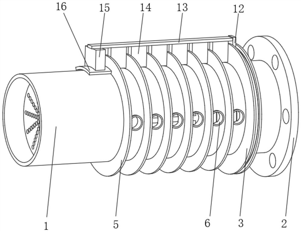
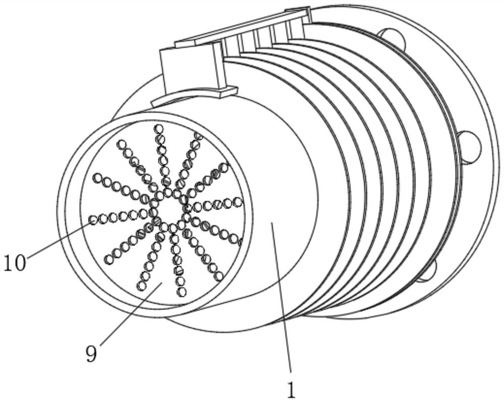
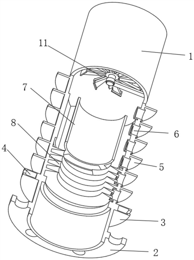
[0036] Such as Figure 1-3 As shown, the present invention provides a technical solution: a heat exchange tube that realizes stable heat exchange based on magnetic self-driving, including a heat exchange inner tube 1, and the output end of the heat exchange inner tube 1 is fixedly connected with a mounting flange 2 , the position of the heat exchange inner tube 1 close to the output end is fixedly connected with the outer limit fin 3, the inside of the outer limit fin 3 extends to the inside of the heat exchange inner tube 1, and the inside of the outer limit fin 3 is located in the heat exchange inner tube The outer position of the tube 1 is provided with a limiting track 4, the outer surface of the heat exchange inner tube 1 and the position at the input end of the outer limiting fin 3 are uniformly and fixedly connected with the heat exchange outer fin 5, and the outer front of the heat exchange inner tube 1 is The position between the heat exchange outer fins 5 is evenly f...
Embodiment 2
[0039] Such as Figure 1-3 As shown, on the basis of Embodiment 1, the present invention provides a technical solution: a heat exchange tube that realizes stable heat exchange based on magnetic self-drive, and the inner sliding connection of the limiting track 4 is connected with a transmission slider 12, and the transmission slider The outer end of 12 is fixedly connected with an outer transmission strut 13, and the bottom surface of the outer transmission strut 13 is uniformly and fixedly connected with a driving stirring piece 14, and the position between the driving stirring piece 14 and the heat exchange outer fin 5 is correspondingly arranged.
[0040] The bottom of the outer transmission strut 13 close to the input end is fixedly connected with a transmission auxiliary block 15, and the bottom of the transmission auxiliary block 15 is fixedly connected with an arc-shaped magnetic block 16, and the arc-shaped magnetic block 16 is correspondingly arranged with the fan driv...
Embodiment 3
[0042] Such as Figure 4 As shown, on the basis of Embodiment 1 and Embodiment 2, the present invention provides a technical solution: a heat exchange tube based on magnetic self-driving to achieve stable heat exchange, and the dispersed heat exchange mechanism 7 includes an inner heat exchange fin 701, The outer side of the inner heat exchange fin 701 is fixedly connected with the heat exchange inner pipe 1, the inner heat exchange slot 702 is provided at the middle position of the inner heat exchange fin 701, and the outer heat exchange slot 703 is evenly opened on the outer side of the inner heat exchange fin 701 . The heat exchange of the heat exchange medium is achieved in different regions, and the local rapid heat exchange of the heat exchange medium is realized.
[0043] One end of the heat exchange groove 6 located inside the heat exchange inner tube 1 is arranged corresponding to the inside of the outer heat exchange tank 703 .
PUM
 Abstract
Description
Claims
Application Information
 - R&D
- Intellectual Property
- Life Sciences
- Materials
- Tech Scout
- Unparalleled Data Quality
- Higher Quality Content
- 60% Fewer Hallucinations
Browse by: Latest US Patents, China's latest patents, Technical Efficacy Thesaurus, Application Domain, Technology Topic, Popular Technical Reports.
© 2025 PatSnap. All rights reserved.Legal|Privacy policy|Modern Slavery Act Transparency Statement|Sitemap|About US| Contact US: help@patsnap.com


