Multi-pass light spot laser emitter

A laser emitter and light spot technology, applied in the direction of instruments, optics, optical components, etc., can solve problems such as low measurement accuracy, lower hit rate of laser emitters, and difficult selection of detection devices

Active Publication Date: 2020-10-27
QINGDAO LASENCE
View PDF6 Cites 0 Cited by
  • Summary
  • Abstract
  • Description
  • Claims
  • Application Information

AI Technical Summary

Problems solved by technology

This state has caused great troubles to the laser receiving end. First, the energy density at the near end and the far end are very different, making it difficult to select detector devices. Second, the large difference in spot size causes difficulties in positioning accuracy and detector layout.
First of all, when the distance between the laser emitter and the detector matrix is ​​relatively close, the divergence angle of the beam emitted by the laser emitter should be larger, so as to prevent the beam from irradiating between the detectors in the detector matrix, reducing the hit rate of the laser emitter; Secondly, when the distance between the laser emitter and the detector matrix is ​​relatively long, the divergence angle of the beam emitted by the laser emitter should be smaller, so as to prevent the light spot from becoming larger after the beam passes through a longer optical path, and more light may be irradiated in the light spot. detectors, making the measurement accuracy low

Method used


Image

  • Multi-pass light spot laser emitter
  • Multi-pass light spot laser emitter
  • Multi-pass light spot laser emitter

Examples


Embodiment 1

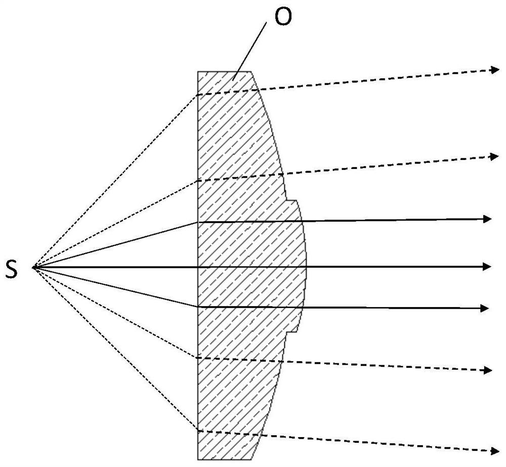
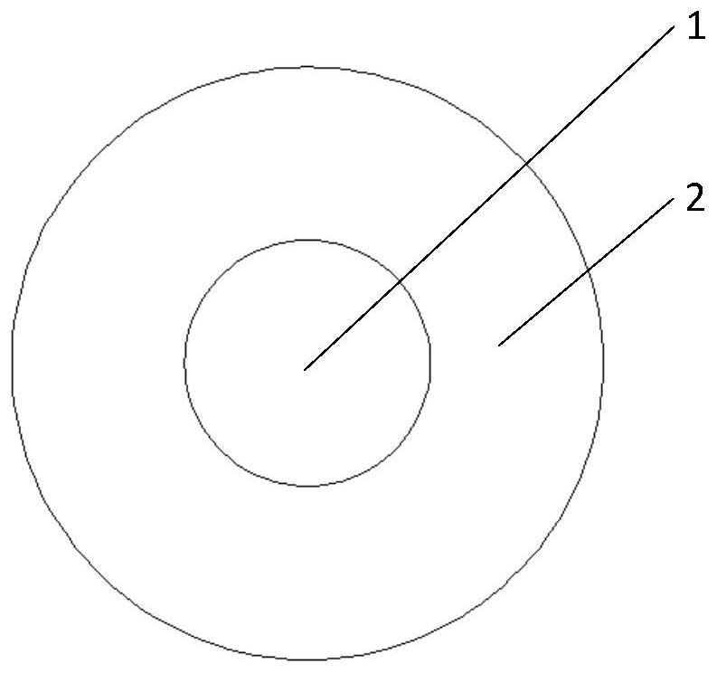
[0023] A laser emitter with multiple passes of light spots includes a laser source S, a lens O, and the lens O contains a plurality of ring-shaped lens areas, such as figure 1 and 2 The lens O in the lens is two ring-shaped lens areas, namely the ring-shaped lens area 1 and the ring-shaped lens area 2. The main optical axes of each ring-shaped lens area are coincident, and the focal lengths are different, so that under the irradiation of a laser emitter, the light passes through different When the lens area, the divergence angle is different.

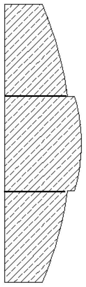
[0024] The lens O can be made of plastic, resin or glass material. When manufacturing the lens, it can be integrally formed, that is, the final shape can be made into a mold, or a larger lens can be prepared through the mold, and then processed to produce different focal lengths. ring lens area, figure 1 The one shown is integrally formed; in addition, the method of assembling can also be adopted, that is, for the convenience of manuf...

Embodiment 2

[0027] A specific structure of a laser emitter with a multi-pass spot, including a laser source S, a lens O, and the lens O includes a plurality of lens areas, and the lens areas are composed of a plurality of fan-shaped areas, and the fan-shaped areas are located perpendicular to the main beam axis of the lens section, and the apex of the fan-shaped area coincides with the intersection of the principal optical axis and the lens section, such as Figure 5 The lens O in the lens is two fan-shaped lens areas, which are respectively fan-shaped lens area 3 and fan-shaped lens area 4. The main optical axes of each fan-shaped lens area are coincident, and the focal lengths are different, so that under the irradiation of a laser emitter, the light passes through different When the lens area, the divergence angle is different.

[0028] The lens O can be made of plastic, resin or glass material. When manufacturing the lens, it can be integrally formed, that is, the final shape can be m...

Embodiment 3

[0031] A specific structure of a laser emitter with a multi-pass spot, including a laser source S, a lens O, and the lens O includes a plurality of lens areas, and the lens areas are composed of a plurality of fan-shaped areas, and the fan-shaped areas are located perpendicular to the main beam axis, and the apex of the fan-shaped area coincides with the intersection of the main optical axis and the lens section; the multiple fan-shaped areas are composed of multiple annular lens areas with different focal lengths. like Figure 7The lens O in is roughly divided into two fan-shaped areas, that is, the first fan-shaped area composed of lens areas 5 and 7, and the second fan-shaped area composed of lens areas 6 and 8, and each fan-shaped area contains two The main optical axes of the four lens areas 5-8 coincide, the centers of the lens areas 5-8 coincide with the vertices of the fan-shaped area, and have different focal lengths. Under the irradiation of a laser emitter, the ligh...


PUM


Abstract

The invention relates to a multi-pass light spot laser emitter. The emitter comprises a laser source and a lens, and is characterized in that the lens comprises a plurality of lens subareas, the mainoptical axes of a plurality of lens subareas coincide and have different focal lengths, and the laser source is arranged on the main optical axis, under irradiation of the laser source, when light passes through different lens zones, divergence angles of the light are different. Through optical shaping system partition or multi-configuration optical system synthesis of the laser transmitting end,multi-configuration output of the laser transmitting system is achieved, the beneficial effect that the sizes of laser multi-pass light spots of a single transmitting unit are similar is achieved, that is, the sizes of the light spots with different detection distances are similar, and therefore model selection and layout of detection devices are greatly simplified.

Description

technical field [0001] The invention relates to the manufacture and application of lasers, in particular to a laser emitter with multi-pass light spots. Background technique [0002] In optical transmitting and receiving systems such as laser communication, laser energy transmission, and laser analog countermeasures, in order to make full use of the directivity and low divergence of lasers, a longer effective working distance is often required. Therefore, the laser emitting end will be adjusted to the state of the small divergence angle of the laser. However, the light spot still gradually becomes larger with the increase of the transmission distance, that is, the size of the light spot at a short distance and a long distance will be very different. This state has caused great troubles to the laser receiving end. First, the energy density at the near end and the far end are very different, making it difficult to select detector devices. Second, the large difference in spot ...

Claims


Application Information

Patent Timeline
Patent Type & Authority Applications(China)
IPC IPC(8): G02B27/09
CPCG02B27/0955G02B27/0927
Inventor 亓玉凯
Owner QINGDAO LASENCE
Why Eureka
Try Eureka