Through hole filling method and structure
A filling method and support structure technology, which is applied to semiconductor/solid-state device parts, semiconductor devices, electrical components, etc., can solve the problem of low filling yield of through holes
- Summary
- Abstract
- Description
- Claims
- Application Information
AI Technical Summary
Problems solved by technology
Method used
Image

Examples
Embodiment Construction
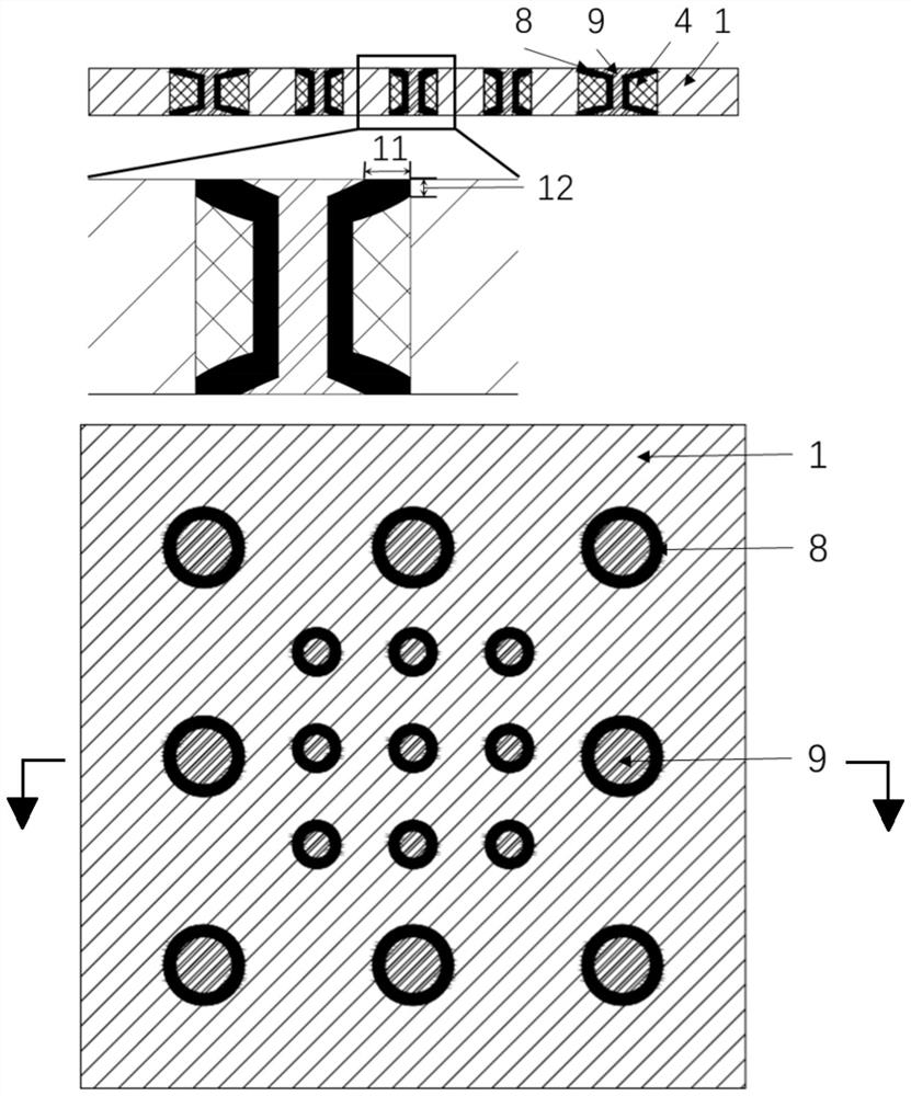
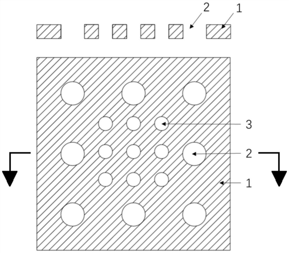
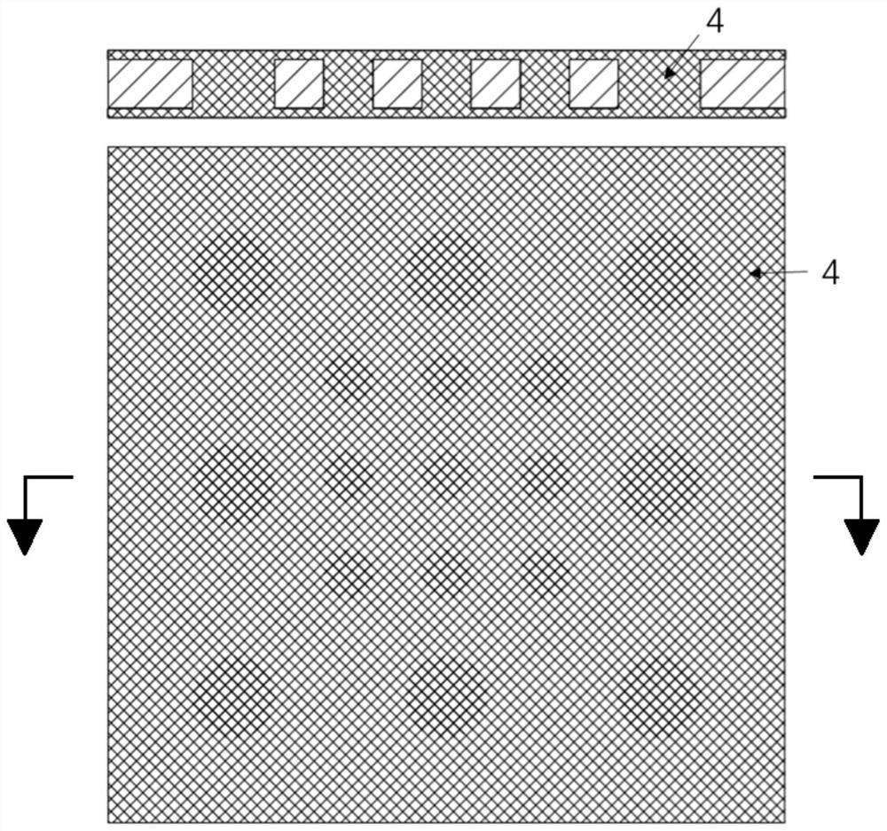
[0041] The through-hole filling method and structure proposed by the present invention will be further described in detail below with reference to the drawings and specific embodiments. Advantages and features of the present invention will be apparent from the following description and claims. It should be noted that all the drawings are in a very simplified form and use imprecise scales, and are only used to facilitate and clearly assist the purpose of illustrating the embodiments of the present invention.
[0042] In addition, unless otherwise stated, features in different embodiments of the present invention can be combined with each other. For example, a feature in the second embodiment may be used to replace a corresponding or functionally identical or similar feature in the first embodiment, and the resulting embodiment also falls within the scope of disclosure or description of the present application.
[0043] The core idea of the present invention is to provide a t...
PUM
 Abstract
Description
Claims
Application Information