
Strong gasflow sealing assembly based on lightning protection and arc extinguishing

A technology of sealing components and strong airflow, applied in electrical components, spark gap parts, spark gaps, etc., can solve the problems of insufficient arc effect, leakage of jet airflow, damage to insulator strings and hardware, etc.

Pending Publication Date: 2020-10-27
王巨丰
View PDF1 Cites 0 Cited by
  • Summary
  • Abstract
  • Description
  • Claims
  • Application Information

AI Technical Summary

Problems solved by technology

[0002] Lightning protection of transmission lines has always been an important part of the lightning protection work of the power sector. Lightning faults are still one of the important factors affecting the safety of the power grid. For a long time, lightning factors have been the main cause of transmission line fault tripping. The flashover of insulators on the transmission line, followed by power frequency freewheeling, damages the insulator strings and fittings, resulting in the burning of the insulator strings and the accident of burning wires. The electric power department generally adopts the transmission line to install the line lightning protection device to achieve this. Protect
The application number of a Chinese patent is: 201610747255.3, and the patent name is: Lightning-induced solid-phase arc-extinguishing lightning arrester. Although the arc-extinguishing lightning arrester has strong arc-extinguishing ability, stable and reliable operation, and quick and convenient replacement of arc-extinguishing gas pellets, However, the jet airflow will leak at the connection between the arc extinguishing turntable and the arc extinguishing cylinder. Considering that the unconcentrated airflow does not have enough effect on the arc, which will lead to the arc extinguishing ability and lightning protection effect of the arc extinguishing and lightning arrester. Therefore, it is hoped that The jet airflow maximizes the effect on the arc and can increase the intensity of the arc extinguishing airflow by improving the sealing of the arc extinguishing airflow channel. Therefore, a strong airflow sealing component based on lightning protection and arc extinguishing is proposed

Method used


Image

  • Strong gasflow sealing assembly based on lightning protection and arc extinguishing
  • Strong gasflow sealing assembly based on lightning protection and arc extinguishing
  • Strong gasflow sealing assembly based on lightning protection and arc extinguishing

Examples


Embodiment 1

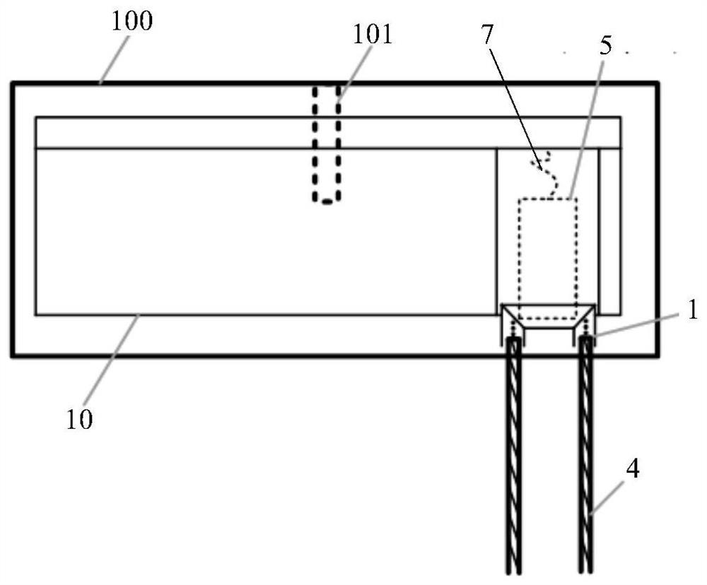
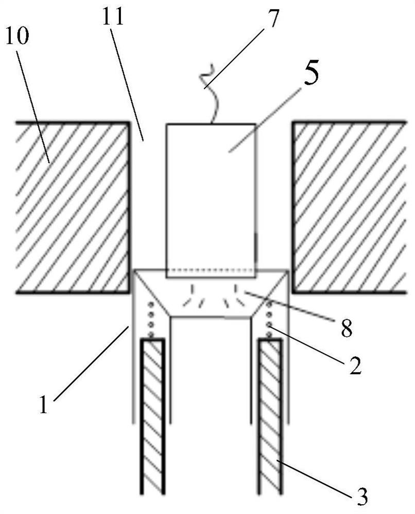
[0025] Example 1: Combining figure 2 As shown, a spring 2 is arranged on the top of the cylindrical cylinder 3, the upper end of the spring 2 is connected with the sealing sleeve 1, and the lower end of the spring 2 is connected with the top end of the cylindrical cylinder 3, so that the sealing Sleeve 1 can slide up and down relative to provide supporting force. Since the inner diameter of sealing sleeve 1 is slightly larger than cylindrical cylinder 3, it can be set on cylindrical cylinder 3, and under the action of spring 2, the sealing sleeve 1 can move up and down within a certain range. Since both the sealing sleeve 1 and the cylindrical cylinder 3 need to have a corresponding thickness as a support, the thickness is about 1-2 cm, and the material must be resistant to high temperature and high pressure, such as polyester fiber.

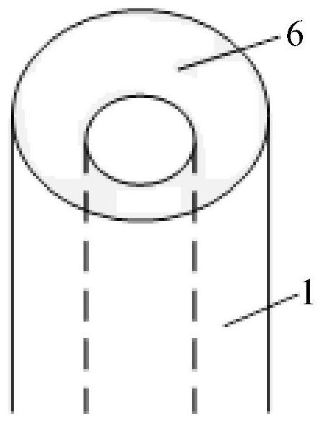
[0026] In the present invention, as image 3 As shown, the bottom end direction of the top end of the sealing sleeve 1 is a concave funnel s...

Embodiment 2

[0027] Embodiment 2: the difference between this embodiment and embodiment 1 is that, as Figure 4 with Figure 5As shown, the upper end of the spring 2 is internally connected with the top end of the sealing sleeve 1 , and the lower end of the spring 2 is connected with the top section of the cylindrical cylinder 3 . In the present invention, as Figure 4 , Figure 5 with Image 6 As shown, a spring hole 4 is provided on the top section of the cylinder 3, and the spring hole 4 extends vertically downward between the inner wall and the outer wall of the cylinder 3, and the middle and lower part of the spring 2 Set in the spring hole 4, the upper end of the spring 2 is internally connected with the top end of the sealing sleeve 1, and the number of spring holes 4 arranged on the top section of the cylindrical cylinder 3 is more than four, each The spring holes 4 are equidistantly distributed on the top section of the cylindrical cylinder 3, and a spring 2 is placed in each ...

Embodiment 3

[0028] Embodiment 3: The difference between this embodiment and Embodiment 1 and Embodiment 2 is that, as Figure 7 with Figure 8 As shown, a shoulder 100 is cut transversely along the center of the sealing sleeve 1 at the outer wall of the middle or middle and lower portion of the sealing sleeve 1, and along the direction of the lower end of the sealing sleeve 1 And a neck 101 is cut between the inner edge of the shoulder 100 and the inner wall of the sealing sleeve 1, so that the sealing sleeve 1 is divided into upper and lower parts. The inner diameters of the upper and lower parts are the same, but the outer diameter of the upper part is The diameter is larger than the outer diameter of the lower part, and the lower part of the sealing sleeve 1 is a thin-walled hollow cylinder, whose outer diameter is slightly smaller than the inner diameter of the cylindrical cylinder, so that the sealing sleeve 1 can expand and contract up and down under the action of the spring 1, and ...


PUM


Abstract

The invention discloses a strong gasflow sealing assembly based on lightning protection and arc extinguishing. The sealing assembly comprises a sealing bush, a cylinder barrel and a rotary disc, wherein a plurality of gas spraying holes uniformly distributed are formed in the disc surface of the rotary disc in the circumferential direction, a gas production assembly for producing strong gasflow ishermetically placed in the gas spraying hole, the sealing bush is mounted at the outlet of the gas spraying hole, when the gas production assembly generates strong gasflow each time, the rotary discrotates by one grid, the outlet of the gas spraying hole is communicated with a spraying inlet in the top end of the sealing bush, and the cylinder barrel is arranged in the sealing bush in a sleevedmode and used for supporting the sealing bush and providing supporting force for sealing communication between the supported sealing bush and the gas spraying hole when the supported sealing bush canslide up and down relatively. The sealing assembly is simple in structure, the oblique section of the sealing sleeve well prevents strong gasflow from leaking, and it can be guaranteed that the generated strong gasflow acts on an electric arc to the maximum extent.

Description

technical field [0001] The invention belongs to the technical field of lightning protection and arc extinguishing, and in particular relates to a strong air flow sealing component based on lightning protection and arc extinguishing. Background technique [0002] Lightning protection of transmission lines has always been an important part of the lightning protection work of the power sector. Lightning faults are still one of the important factors affecting the safety of the power grid. For a long time, lightning factors have been the main cause of transmission line fault tripping. The flashover of insulators on the transmission line, followed by power frequency freewheeling, damages the insulator strings and fittings, resulting in the burning of the insulator strings and the accident of burning wires. The electric power department generally adopts the transmission line to install the line lightning protection device to achieve this. Protect. The application number of a Chine...

Claims


Application Information

Patent Timeline
IPC IPC(8): H01T1/08
CPCH01T1/08
Inventor 王巨丰王嬿蕾周勇军王国锋黄萍
Owner 王巨丰
Learn More