Module safety control protection and indication circuit based on IGBT driving
A technology for driving modules and indicating circuits, applied in circuit breaker testing, electrical components, electronic switches, etc., can solve problems such as poor anti-interference, inconvenient testing, and unstable IGBT driver protection values.
- Summary
- Abstract
- Description
- Claims
- Application Information
AI Technical Summary
Problems solved by technology
Method used
Image
Examples
Embodiment 1
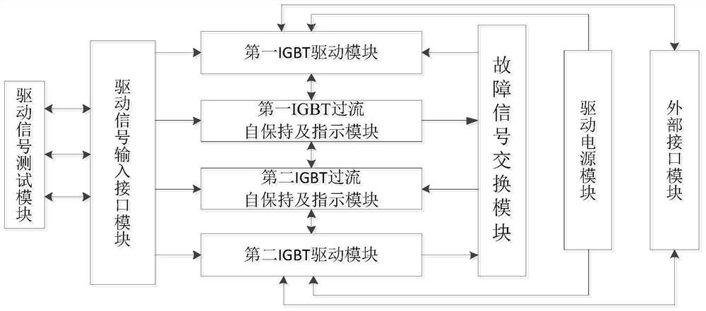
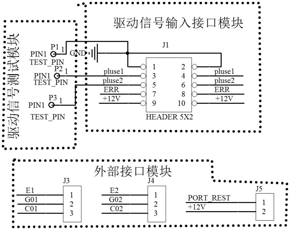
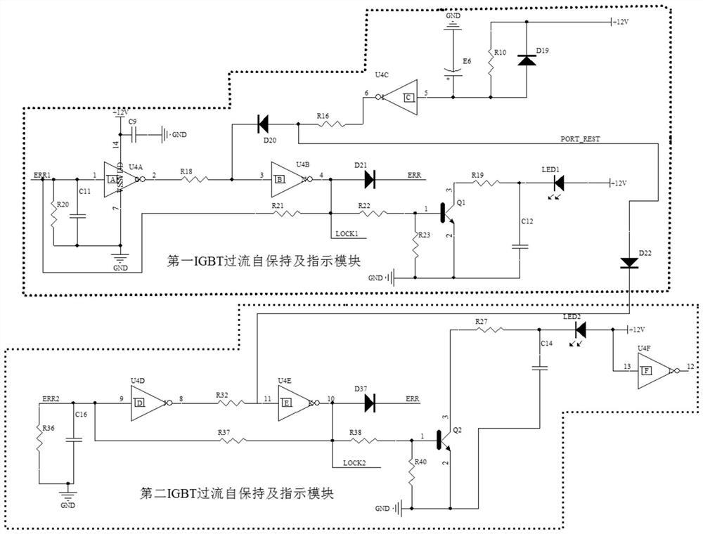
[0037] Such as figure 1 As shown, a module safety control protection and indication circuit based on IGBT drive includes a drive signal test module, a drive signal input interface module, a fault signal conversion module, a drive power supply module, a first IGBT drive module, a second IGBT drive module, The first IGBT over-current self-holding and indicating module, the second IGBT over-current self-holding and indicating module and an external interface module;
[0038] The output end of the drive signal test module is connected to the input end of the drive signal input interface module, and the output end of the drive signal input interface module is respectively connected to the IGBT upper bridge arm signal input end (pluse1) of the first IGBT drive module and the second IGBT drive module. The IGBT lower bridge arm signal input terminal (pluse2), the first IGBT overcurrent self-holding and indication module total fault signal output (ERR) and the second IGBT over-current ...
Embodiment 2
[0081] In this embodiment, the path direction of each signal when the module safety protection and indication circuit is working is provided:
[0082] Path 1: eg Figure 7 As shown, the power chip U1 in the drive power module generates DC+15V1 working power. When the DC24V power is sent to pin 1 and pin 2 of the terminal J2, L passes through D1 and D2 to chip U1 (power module DC24V becomes DC+15V1 , with E1(DC-9V));
[0083] Path 2: as in Figure 7 As shown, the power chip U3 in the power drive module generates DC+15V2 working power. When the DC24V power is sent to the terminal J2, pin 1, and pin 2, it passes through diodes D1 (diode) and D2 (diode) to U2 (power module DC24V Change DC+15V2, filtered by capacitor E1 and E2 (DC-9V) filtered by capacitor E2).
[0084] Path 3: as in Figure 8 As shown, the drive pulse input signal interface, J2 (drive pulse input signal interface), provides GND (power common terminal), pluse1 (IGBT upper bridge arm input signal), pluse2 (IGBT ...
PUM
 Abstract
Description
Claims
Application Information
 - R&D
- Intellectual Property
- Life Sciences
- Materials
- Tech Scout
- Unparalleled Data Quality
- Higher Quality Content
- 60% Fewer Hallucinations
Browse by: Latest US Patents, China's latest patents, Technical Efficacy Thesaurus, Application Domain, Technology Topic, Popular Technical Reports.
© 2025 PatSnap. All rights reserved.Legal|Privacy policy|Modern Slavery Act Transparency Statement|Sitemap|About US| Contact US: help@patsnap.com


