Cavity self-adaption device
An adaptive and cavity technology, applied in the field of medical devices, can solve the problem that the anchoring device of the occluder cannot adapt to the anatomical shape of the left atrial appendage, etc.
- Summary
- Abstract
- Description
- Claims
- Application Information
AI Technical Summary
Problems solved by technology
Method used
Image
Examples
Embodiment 1
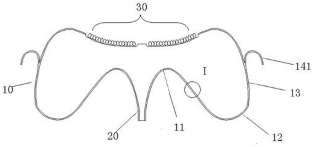
[0091] Such as Figure 1a-Figure 1f Among them, this embodiment provides an adaptive cavity device, which includes a central end portion 20 and an anchoring bracket 10 , and the anchoring bracket 10 is surrounded by a plurality of elastic support rods emanating from the central end portion 20 . Such as Figure 1a and 1c Among them, the support rod extends concavely from the central end 20 toward the distal end to form a first curved portion 11, and extends outwardly from the end of the first curved portion 11 away from the central end 20 toward the proximal end to form a second curved portion 12. One end of the second curved portion 12 away from the first curved portion 11 extends in the distal direction to form a transition portion 13; a plurality of support rods are circumferentially rotationally symmetrical along the central axis of the central end portion 20 to form a bowl-shaped anchoring bracket 10; In the transition portion 13, a plurality of support rods are connecte...
Embodiment 2
[0099] Such as Figure 4a-4b Among them, the self-adaptive cavity device provided in this embodiment is based on the device provided in Embodiment 1, and further includes a first flow blocking film 40, the first flow blocking film 40 is composed of a multi-layer coating film, and the multi-layer The coating film covers the support rods of the anchoring bracket 10, such as Figure 4a shown. The anchoring stent 10 is provided with a membrane connecting structure, which is one or more coils 15 and a limiting structure 16, such as Figure 4b In the process, the coil 15 cooperates with the limiting structure 16 to connect the covering film to the anchoring stent 10, so that the first blocking membrane 40 will not fall off or be damaged when the device is put in and out of the sheath.
[0100] In this embodiment, the central end 20 is provided with a detachable connection structure, which is convenient for connection with the transmission cable.
[0101] In this embodiment, the c...
Embodiment 3
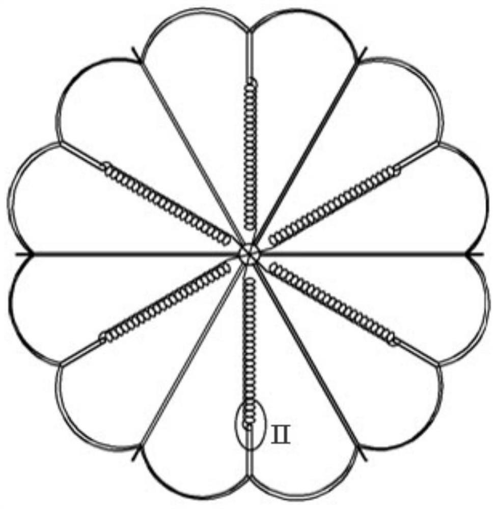
[0103] Such as Figures 5a-5d Among them, the adaptive cavity device provided in this embodiment is based on the device provided in Embodiment 1. The first difference between Embodiment 3 and Embodiment 1 is that each three-dimensional spiral structure of the converging part 30 , that is, the spring emanates from its central point and is spirally divergent relative to the central axis of the central end 20, rather than radially divergent, such as Figure 5c, and the number and position of the support rods correspond to the springs one-to-one, the 6 support rods are connected to one end of the 6 springs, and the other ends of the 6 springs converge to form a collection point.
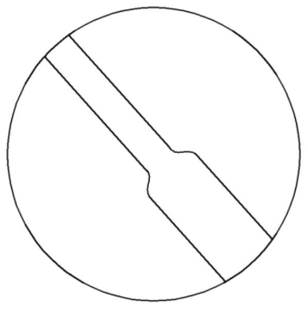
[0104] The second difference is that: the first bending portion 11, the second bending portion 12 and the transition section 13 of the anchoring bracket 10 are provided with adaptive structures, such as Figure 5b Among them, it is a two-dimensional S-shaped structure, and the solid rod width of the two...
PUM
 Abstract
Description
Claims
Application Information
 - R&D
- Intellectual Property
- Life Sciences
- Materials
- Tech Scout
- Unparalleled Data Quality
- Higher Quality Content
- 60% Fewer Hallucinations
Browse by: Latest US Patents, China's latest patents, Technical Efficacy Thesaurus, Application Domain, Technology Topic, Popular Technical Reports.
© 2025 PatSnap. All rights reserved.Legal|Privacy policy|Modern Slavery Act Transparency Statement|Sitemap|About US| Contact US: help@patsnap.com


