Surgical instrument for mounting acetabular cup

A technology for surgical instruments and acetabular cups, applied in the acetabular socket, hip joint, medical science and other directions, can solve the problems of reduced performance of surgical instruments, thread damage and deformation, shortened service life, etc., to reduce the possibility of deformation, The effect of increasing the contact surface and improving the cushioning effect

Active Publication Date: 2020-10-30
BEIJING CHUNLIZHENGDA MEDICAL INSTR
View PDF12 Cites 2 Cited by
  • Summary
  • Abstract
  • Description
  • Claims
  • Application Information

AI Technical Summary

Problems solved by technology

During the hammering process, since the acetabular cup is located in the acetabular socket, hammering will only make the acetabular cup press against the acetabular socket, so there is no relative displacement tendency, but the screw joint is different, hammering will make the screw joint Continue to push inward, and there is a tendency of displacement relative to the acetabular cup. During the process of pushing inward, the threads of the helical joint will interact with the pole hole threads of the acetabular cup, resulting in greater stress. Long-term use is easy Causes thread damage and deformation on the screw connector, resulting in reduced performance and reduced service life of the surgical instrument
[0004] In view of the related technologies mentioned above, the inventor believes that there is a defect that the thread on the screw joint is easily deformed

Method used


Image

  • Surgical instrument for mounting acetabular cup
  • Surgical instrument for mounting acetabular cup
  • Surgical instrument for mounting acetabular cup

Examples


Embodiment 1

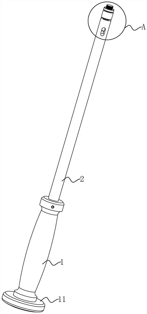
[0041] refer to figure 1 , the handle 1 is columnar, and its end away from the installer connecting rod 2 is fixedly connected with a bearing plate 11. The diameter of the bearing plate 11 is larger than that of the handle 1, and is mainly used to increase the force-bearing area so that the medical staff can hammer accurately.

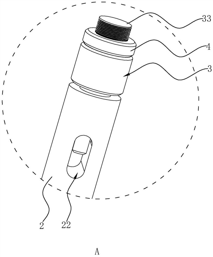
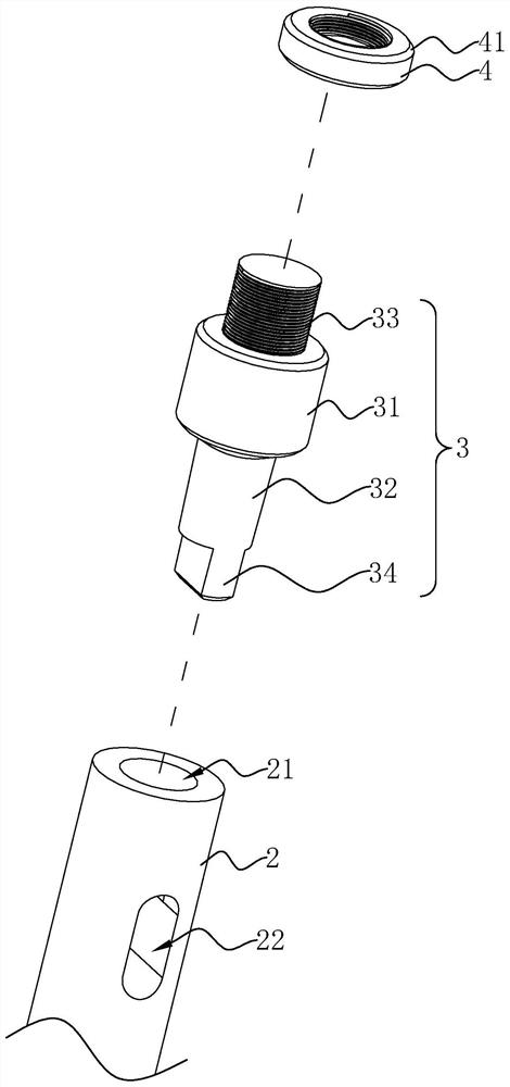
[0042] refer to figure 2 and image 3 , the screw joint 3 includes a cylinder 31, one end of the cylinder 31 is formed with an insertion rod 32, and the other end of the cylinder 31 is formed with a threaded rod 33; The screw joint 3 and the installer connecting rod 2 are fixed through the interference fit between the insertion rod 32 and the socket 21 . After the insertion rod 32 and the socket 21 are interference-fitted, there is an insertion gap between the cylinder 31 and the end of the installer connecting rod 2. The setting of the insertion gap enables medical personnel to insert into the insertion gap through tools. Inside, the spiral joint ...

Embodiment 2

[0050] The difference between this embodiment and embodiment 1 is that, referring to Figure 5 , the uniform force structure is a uniform force ring 6 with certain elasticity, one side of the uniform force ring 6 is fixedly connected with the buffer pad 4, and the uniform force ring 6 gradually moves from the side close to the buffer pad 4 to the side away from the buffer pad 4 Shrink inward, and form a closed structure with a curved surface on the side of the equalizing ring 6 away from the buffer pad 4. The closed structure can fit the inner wall of the acetabular cup through the curved surface. When the trend of displacement, the equalizing ring 6 presses against the acetabular cup, and evenly transmits the hammering force to the acetabular cup, which acts as a buffer and reduces the thread of the screw joint 3 and the pole hole of the acetabular cup Interaction forces between threads.

Embodiment 3

[0052] The difference between this embodiment and embodiment 1 is that, as Figure 6 As shown, the uniform force structure is a plurality of uniform force plates 7 centered on the threaded rod 33 and distributed around the circumference. The buffer pad 4 is fixed, and the other end is bent towards the threaded rod 33. This structural design enables the end of the equalizer 7 away from the buffer pad 4 to be better attached to the inner wall of the acetabular cup after the acetabular cup is installed. , evenly transmit the impact force, and at the same time, play a good buffering effect.


PUM


Abstract

The invention relates to the field of acetabular cup installation, and particularly relates to a surgical instrument for mounting an acetabular cup. The surgical instrument comprises a handle and an installer connecting rod fixedly connected to one end of the handle. The surgical instrument further comprises a spiral connector detachably installed at the end, away from the handle, of the installerconnecting rod, and a buffering cushion used for abutting against the inner wall of the installed acetabular cup is arranged on the spiral connector. The surgical instrument has the effect of reducing the possibility of deformation of the threads on the screw joint.

Description

technical field [0001] The present application relates to the field of acetabular cup installation, in particular to a surgical instrument for acetabular cup installation. Background technique [0002] The acetabular cup needs to use corresponding surgical instruments during the installation process. The current surgical instruments are mainly composed of three parts, namely the handle, the installer connecting rod fixed on the handle, and the screw joint integrally formed with the installer connecting rod. Among them, the screw joint is located at the end of the connecting rod of the installer. During the operation, the screw joint on the screw rod is connected with the threaded hole on the acetabular cup. Vigorous hammering is performed to implant the acetabular cup into the acetabular fossa, and then the acetabular cup is finally fixed with screws. After the fixation is completed, the surgical instruments are removed to prepare for the next operation. [0003] Due to the...

Claims


Application Information

Patent Timeline
Patent Type & Authority Applications(China)
IPC IPC(8): A61F2/46
CPCA61F2/4609A61F2002/4615
Inventor 史春宝解凤宝候惠欣郝孟娟
Owner BEIJING CHUNLIZHENGDA MEDICAL INSTR
Why Eureka
Try Eureka