A gear cleaning device for machining

A technology of machining and cleaning device, applied in the field of machining, can solve the problems of lack of direct brushing of gears, poor cleaning effect, etc., and achieve the effects of convenient access, improved anti-skid performance, and improved cleaning effect

Active Publication Date: 2022-07-19
乔崴进(安徽)科技有限公司
View PDF15 Cites 0 Cited by
  • Summary
  • Abstract
  • Description
  • Claims
  • Application Information

AI Technical Summary

Problems solved by technology

However, the structural design of the above-mentioned patent is relatively simple. In the actual use process, there is a lack of direct brushing of the gears, especially the cleaning effect of the gear tooth gaps is poor, so there are certain limitations.

Method used


Image

  • A gear cleaning device for machining
  • A gear cleaning device for machining
  • A gear cleaning device for machining

Examples


Embodiment 1

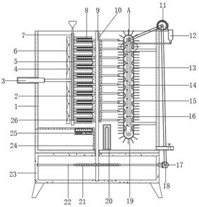
[0030] refer to Figure 1-4 , a gear cleaning device for machining, including a cleaning cylinder 1, the bottom outer wall of the cleaning cylinder 1 is fixed with a transmission bottom case 23 by bolts, and the transmission bottom case 23 and the cleaning cylinder 1 are rotatably connected with the same rotating column 9 through a bearing, and the rotating One side of the circumferential outer wall of the column 9 is welded with a convex key 10, and the outer wall of the rotating column 9 is staggered with gears and a spacer 5 in turn, and a first-order cleaning mechanism and a second-order cleaning mechanism are respectively installed on both sides of the cleaning drum 1, and the first-order cleaning mechanism. The cleaning mechanism includes a mounting frame 13 fixed on one side of the inner wall of the cleaning cylinder 1 by bolts. Both ends of the mounting frame 13 are connected with round rollers through bearings, and the outer walls of the two round rollers are sleeved w...

Embodiment 2

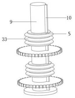
[0041] refer to Figure 5 , a gear cleaning device for machining. Compared with Embodiment 1, this embodiment also includes that the circumferential outer wall of the spacer 5 is welded with equidistantly distributed oblique convex rings 33, and the angle between the inclined convex ring 33 and the spacer 5 is welded. is an acute angle.

[0042] When the present invention is used, the oblique convex ring 33 is arranged on the circumferential outer wall of the spacer 5 to effectively improve the anti-skid performance of the spacer 5, thereby achieving the purpose of facilitating the taking and placing of the spacer 5.


PUM


Abstract

The invention belongs to the technical field of mechanical processing, in particular to a gear cleaning device for mechanical processing. Aiming at the problems that most of the traditional gear cleaning devices are relatively simple in structure, lack of direct brushing treatment for the gears, and have poor cleaning effect, the following solutions are now proposed. , including a cleaning cylinder, the bottom outer wall of the cleaning cylinder is fixed with a transmission bottom box by bolts, the transmission bottom box and the cleaning cylinder are rotatably connected to the same rotating column through a bearing, and one side of the circumferential outer wall of the rotating column is welded with a convex The outer wall of the rotating column is staggered with gears and spacers in sequence, and a first-order cleaning mechanism and a second-order cleaning mechanism are respectively installed on both sides of the cleaning barrel. The present invention can drive the transmission belt to rotate through the first belt, and at the same time, through the transmission action of the second belt, the conical teeth, the worm and the worm gear ring, the rotating motor drives the rotating column to rotate slowly, and then cooperates with the brush bristles to the gears. Effective cleaning of tooth gaps.

Description

technical field [0001] The invention relates to the technical field of machining, in particular to a gear cleaning device for machining. Background technique [0002] Machining refers to the process of changing the dimensions or properties of a workpiece through a mechanical device. According to the difference in processing methods, it can be divided into cutting processing and pressure processing. Mechanical parts, also known as mechanical components, are the basic components that constitute machinery, and are inseparable single parts that make up machinery and machines. Gears are common mechanical parts, which refer to mechanical elements that continuously mesh with gears on the rim to transmit motion and power. The application of gears in transmission appeared very early. At the end of the 19th century, the principle of the gear cutting method and the special machine tools and tools that used this principle to cut teeth appeared one after another. With the development ...

Claims


Application Information

Patent Timeline
Patent Type & Authority Patents(China)
IPC IPC(8): B08B3/12B08B3/08B08B3/10B08B1/02B08B1/00
CPCB08B3/123B08B3/08B08B3/10B08B1/02B08B1/002
Inventor 郝明明吴飞亚代子能
Owner 乔崴进(安徽)科技有限公司
Why Eureka
Try Eureka