
Mold core for valve body casting and valve body wax pattern forming die

A molding die and core technology, applied in casting molding equipment, casting mold components, casting molds, etc., can solve the problems of many process steps, high cost, and reduced product consistency.

Pending Publication Date: 2020-10-30
四川省简阳川田机械阀业有限公司
View PDF0 Cites 4 Cited by
  • Summary
  • Abstract
  • Description
  • Claims
  • Application Information

AI Technical Summary

Problems solved by technology

Usually, the valve body of the globe valve is cast by the lost wax method. During the lost wax casting process, it is necessary to make a wax pattern that mimics the finished product. See Figure 9 , in the traditional casting process, the valve body wax pattern 100 is formed by combining and welding multiple blocks, and multiple sets of molds are required to form each block separately. Using this mode to make wax patterns not only has many process steps and high cost, but also the number of workpieces is high. The transfer between stations and the introduction of welding technology will lead to a decrease in the consistency of the entire product, and there will be a greater quality risk

Method used


Image

  • Mold core for valve body casting and valve body wax pattern forming die
  • Mold core for valve body casting and valve body wax pattern forming die
  • Mold core for valve body casting and valve body wax pattern forming die

Examples


Embodiment Construction

[0025] Referring to the accompanying drawings, specific embodiments of the present invention will be described in detail.

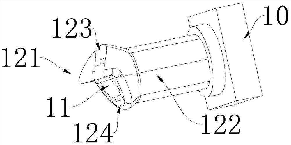
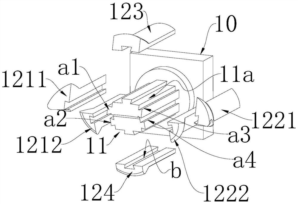
[0026] see figure 1 , an embodiment of a valve body core, including a base 10, on which a central core-pulling block 11 is arranged, and the central core-pulling block 11 includes a prism segment 11c, and the cross-section of the central core-pulling block 11 In order to be polygonal, each internal angle of the polygon is equal to or greater than 90° and less than 180°, the outer wall of the central core pulling block 11 is connected to the parting block 12 through a concave-convex fit structure, and the exposed surface of each parting block 12 is provided with a molding surface , There is a smooth transition between the molding surfaces of adjacent sub-core blocks, the tail of the prism section 11c is connected to the fixed tailstock 12, and the tail of the split block 12 abuts against the end surface of the positioning seat. Preferably. The side of eac...


PUM


Abstract

The invention relates to a mold core for valve body casting and a valve body wax pattern forming die. The valve body wax pattern forming die comprises an upper die body, a lower die body and the moldcore. The upper die body is buckled to the lower die body, a cavity is formed in the joint surface of the upper die body and the lower die body and communicates with the outside through a wax ejectionport in the side wall, and the cavity communicates with the outside through a first mounting hole, a second mounting hole and a third mounting hole. The first mounting hole internally cooperates witha first mold core for forming an upper flow channel of a shut-off valve, the second mounting hole internally cooperates with a second mold core for forming a valve rod hole of the shut-off valve, andthe third mounting hole internally cooperates with a third mold core for forming a lower flow channel for the shut-off valve. The end, close to the second mold core, of the first mold core is provided with a lateral forming concave surface matched with a lateral protrusion on the second mold core, the second mold core is internally provided with a locking rod extending in the axial direction of the second mold core, the inner extending end of the locking rod penetrates through a column used for forming a valve flap hole and is fixedly connected with a corresponding connecting hole in the third mold core, and the two end surfaces of the column abut against the second mold core and the third mold core respectively.

Description

technical field [0001] The invention relates to a molding device, in particular to a core for casting a valve body and a valve body wax pattern forming mold. Background technique [0002] Globe valves can be used to control the flow of various types of fluids such as air, water, steam, various corrosive media, mud, and oil. Very suitable for cutting and throttling. Because the valve stem of this type of valve has a relatively short opening or closing stroke, it has a very reliable cut-off function. Usually, the valve body of the globe valve is cast by the lost wax method. During the lost wax casting process, it is necessary to make a wax pattern that mimics the finished product. See Figure 9 , in the traditional casting process, the valve body wax pattern 100 is composed of multiple blocks combined and welded, which requires multiple sets of molds to form each block separately. Using this mode to make wax patterns not only has many process steps and high cost, but also the...

Claims


Application Information

Patent Timeline
IPC IPC(8): B22C9/10B22C9/04B22C7/02
CPCB22C7/02B22C9/04B22C9/103
Inventor 陈鑫丁炤彦
Owner 四川省简阳川田机械阀业有限公司
Learn More