Quick cooling device for continuous degreasing sintering furnace
A rapid cooling, degreasing and sintering technology, applied in the field of cooling equipment, can solve problems such as low efficiency and long cooling process time
- Summary
- Abstract
- Description
- Claims
- Application Information
AI Technical Summary
Problems solved by technology
Method used
Image
Examples
Embodiment 1
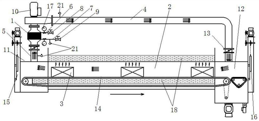
[0030] This embodiment provides a rapid cooling device for continuous degreasing sintering furnace, such as figure 1 As shown, it includes a condenser 1, a circulating fan 10 and a cooling box 2, and a conveying device is arranged in the cooling box 2, and the conveying device is used to convey a material boat 3, and products sintered at high temperature are placed in the material boat 3; the circulating fan 10. One end communicates with the cooling box 2 through the air inlet pipe 4, and the other end communicates with the cooling box 2 through the air extraction pipe 5. The air extraction pipe 5 communicates with the condenser 1, and the condenser 1 is respectively provided with a liquid inlet 6 and a A liquid inlet ball valve 8 is installed on the liquid discharge port 7 and the liquid inlet port 6, and a liquid discharge ball valve 9 is installed on the liquid discharge port 7; a thermocouple is respectively arranged on the liquid discharge port 7, the air intake pipe 4 and...
Embodiment 2
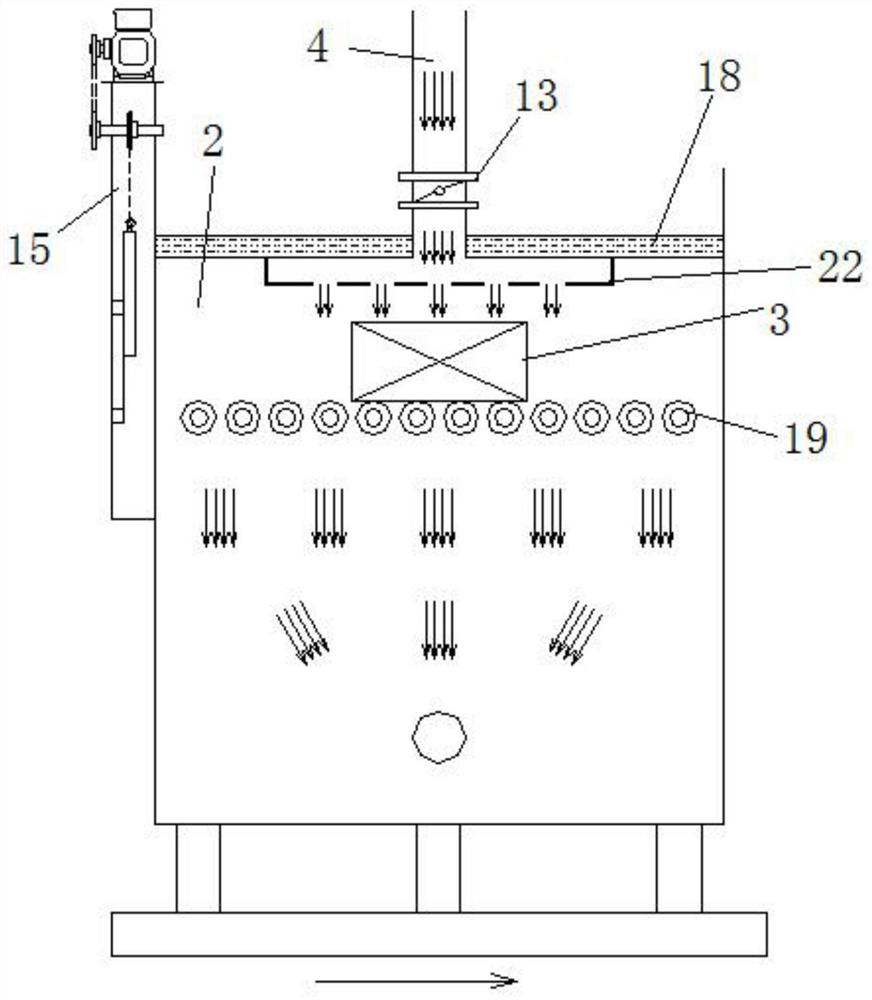
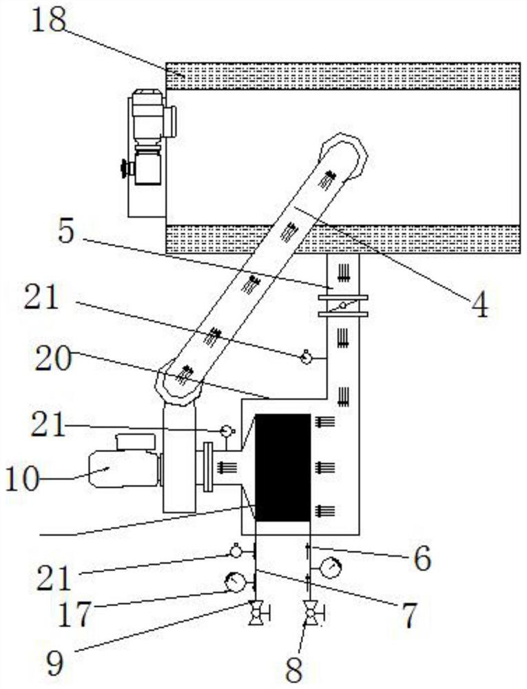
[0034] This embodiment is an improved structure of the first embodiment, the working principle is the same, on the basis of the first embodiment, as figure 2 and image 3 As shown, the cooling inlet sealing gate 15 of the present embodiment is arranged on the cooling box 2, the top of the cooling box 2 is connected with an air intake pipe 4, the air intake pipe 4 is connected with a butterfly valve 13, and the air intake pipe 4 is connected with a circulating fan 10. A condenser 1; the condenser 1 is fixedly installed in the external box body 20, and the side of the bottom end of the cooling box body 2 is connected with an air extraction pipeline 5, and the air extraction pipeline 5 communicates with the external box body 20. Pressure gauges 17 are respectively installed on the liquid inlet 6 and the liquid outlet 7 of the condenser 1 . The side wall of the cooling box 2 is provided with a jacket 18 which continuously replaces the cooling solution. The conveying device is c...
Embodiment 3
[0036] This embodiment is an improved structure of the second embodiment, on the basis of the second embodiment, such as Figure 4 and Figure 5 As shown, the condenser 1 of this embodiment is arranged inside the cooling box body 2, the cooling inlet sealing gate 15 is arranged on the cooling box body 2, the top of the cooling box body 2 is connected with an air inlet pipe 4, and the air inlet pipe 4 is connected to the cooling box body 2 There is a split hole at the communication position. The end of the air intake pipe 4 communicates with the condenser 1 in the cooling box 2 through the circulation fan 10; the side of the bottom of the cooling box 2 is connected with an air extraction pipe 5, and the air extraction pipe 5 is connected with the circulation fan; the air intake pipe 4 is connected with Butterfly valve13. The conveying device is conveying rollers 19 evenly arranged in the cooling box 2 . The side wall of the cooling box 2 is provided with a jacket 18 which co...
PUM
 Abstract
Description
Claims
Application Information
 - R&D
- Intellectual Property
- Life Sciences
- Materials
- Tech Scout
- Unparalleled Data Quality
- Higher Quality Content
- 60% Fewer Hallucinations
Browse by: Latest US Patents, China's latest patents, Technical Efficacy Thesaurus, Application Domain, Technology Topic, Popular Technical Reports.
© 2025 PatSnap. All rights reserved.Legal|Privacy policy|Modern Slavery Act Transparency Statement|Sitemap|About US| Contact US: help@patsnap.com


