Manipulator based on automatic control

A technology of automatic control and manipulators, applied in the direction of program control manipulators, manipulators, manufacturing tools, etc., can solve the problems of high production cost, difficulty in the strength of the manipulator arm, unfavorable repair and maintenance, etc.

Active Publication Date: 2020-10-30
WUXI PROFESSIONAL COLLEGE OF SCI & TECH
View PDF16 Cites 8 Cited by
  • Summary
  • Abstract
  • Description
  • Claims
  • Application Information

AI Technical Summary

Problems solved by technology

[0003] At present, the mainly used mechanical arm mainly clamps and lifts the goods by means of air pressure. It is difficult to control the strength of the mechanical arm. It needs a large number of internal structures and throttle valves to cooperate with the work. The production cost is relatively high, and electric-to-air conversion is required. and other ways, which is not conducive to repair and maintenance

Method used


Image

  • Manipulator based on automatic control
  • Manipulator based on automatic control
  • Manipulator based on automatic control

Examples


Embodiment Construction

[0029] The present invention will be further described below in conjunction with the accompanying drawings.

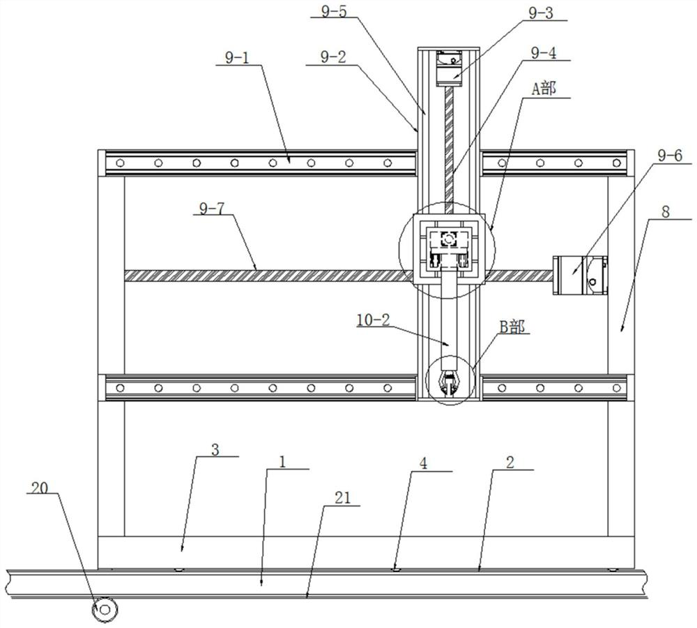
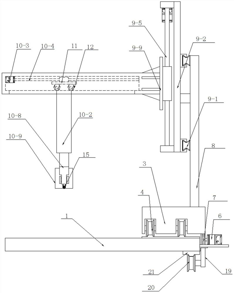
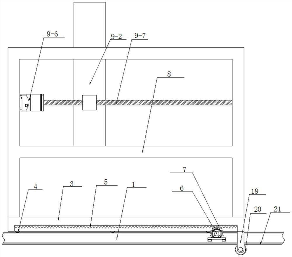
[0030] see as Figure 1-Figure 7 As shown, the technical solution adopted in this specific embodiment is: it includes the operating table 1, the base 3, the guide wheel 4 and the No. 1 guide rail 2, and the rear side of the operating table 1 top is fixed with the No. 1 guide rail 2 by bolts, and the No. 1 guide rail 2 is provided with a base 3, and the inside of the base 3 is embedded with several guide wheels 4 through the rotation of the wheel shaft. The several guide wheels 4 are all rolled on the corresponding No. 1 guide rail 2, and the several guide wheels 4 are arranged in two rows. It also includes No. 1 motor 6, position adjustment mechanism 9 and clamping mechanism 10; the inner top surface of the groove provided on the rear side wall of the base 3 is fixedly welded with a rack 5, and one side of the rear side wall of the console 1 A No. 1 motor 6 of 60KTYZ ...


PUM


Abstract

The invention relates to the technical field of mechanical equipment, in particular to a manipulator based on automatic control. A vertical plate is arranged on the front side of a sliding rail, and the rear side of the vertical plate is slidably arranged on the sliding rail through a sliding block; the rear side wall of the vertical plate is fixedly connected with a nut which is in threaded connection with a first lead screw; an adjusting plate is movably arranged on the front side of the vertical plate, and the rear side wall of the adjusting plate is fixedly connected with a nut in threadedconnection with a second lead screw; a cross beam is vertically and fixedly arranged on the front side wall of the adjusting plate, and a clamping mechanism is arranged on the lower side of the crossbeam; clamping arms are symmetrically and rotationally arranged on the left and right sides of the lower end of an internal thread pipe through rotating shafts and bearings; and clamping plates are movably connected to the lower ends of the clamping arms on the left side and the right side through hinge pieces, the manipulator is driven by a motor to move, no structures such as an air throttle needs to be adopted for cooperative work, the manufacturing cost and energy consumption are reduced, the whole device is convenient to repair and maintain through motor driving, and the cargo clamping force can be effectively controlled in the cargo clamping process.

Description

technical field [0001] The invention relates to the technical field of mechanical equipment, in particular to a manipulator based on automatic control. Background technique [0002] A manipulator is an automatic operating device that can imitate certain movement functions of the human hand and arm to grab, carry objects or operate tools according to a fixed program. It is characterized in that it can be programmed to complete various expected operations. It combines the advantages of both human and robotic machines. At present, it is mainly driven by hydraulic pressure, pneumatic power and mechanical drive. [0003] At present, the mainly used mechanical arm mainly clamps and lifts the goods by means of air pressure. It is difficult to control the strength of the mechanical arm. It needs a large number of internal structures and throttle valves to cooperate with the work. The production cost is relatively high, and electric-to-air conversion is required. And other ways to c...

Claims


Application Information

Patent Timeline
Patent Type & Authority Applications(China)
IPC IPC(8): B25J9/02B25J15/08B25J9/10B25J9/12
CPCB25J9/02B25J15/08B25J9/1035B25J9/12Y02P90/02
Inventor 武彩霞刘荣奎
Owner WUXI PROFESSIONAL COLLEGE OF SCI & TECH
Why Eureka
Try Eureka