
Aircraft fuel tank inerting system and fuel tank explosion-proof method

A fuel tank and aircraft technology, applied in the field of aviation systems, can solve the problems of high inlet pressure of separation membrane, pollution of the environment, low efficiency of separation membrane, etc.

Active Publication Date: 2020-10-30
CHONGQING JIAOTONG UNIVERSITY
View PDF12 Cites 3 Cited by
  • Summary
  • Abstract
  • Description
  • Claims
  • Application Information

AI Technical Summary

Problems solved by technology

[0005] However, there are still many problems in the OBIGGS technology, such as the low efficiency of the separation membrane leading to large aircraft compensatory losses, the high demand pressure at the inlet of the separation membrane makes it unusable on many aircraft models (such as helicopters), the gradual clogging of small membrane filaments and permeable pores, and the Ozone in the source causes serious membrane performance attenuation, and fuel vapor leaks out to pollute the environment when nitrogen-rich gas fills the fuel tank, etc.

Method used


Image

  • Aircraft fuel tank inerting system and fuel tank explosion-proof method
  • Aircraft fuel tank inerting system and fuel tank explosion-proof method

Examples


Embodiment 1

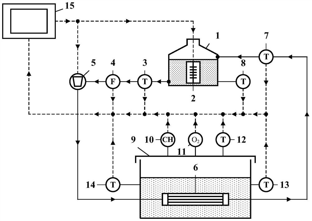
[0024] like figure 1 As shown, an aircraft fuel tank inerting system includes a heat exchanger 6 placed in the fuel tank 9, and the heat exchanger 6 is connected with a heating system. In this embodiment, the heating system includes a water pump 5 and a water tank 1 connected by pipelines. The outlet of the water tank 1 is connected to the water pump 5 by pipelines. A heater 2 is installed.

[0025] Both the heater 2 and the water pump 5 are connected to the controller 15, the pipeline between the water tank 1 and the water pump 5 is equipped with a first temperature sensor 3 and a first flow sensor 4, and the liquid phase space of the water tank 1 is connected with a third temperature sensor through a probe rod. Sensor 8, the pipeline between the heat exchanger 6 and the inlet of the water tank 1 is equipped with a second temperature sensor 7 .

[0026] The upper gas phase space of the fuel tank 9 is connected with a hydrocarbon concentration sensor 10, an oxygen concentrat...

Embodiment 2

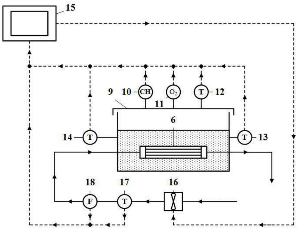
[0030] like figure 2 As shown, the structure of embodiment 2 is basically the same as that of embodiment 1. The difference is that the heating system in this embodiment includes an engine bleed air pipeline, and the engine bleed air pipeline is connected to a fan 16 through a pipeline, and the downstream of the fan 16 is connected to the heat exchanger 6 , The heat exchanger 6 outlet pipes are connected to the outside of the machine. The fan 16 is connected to the controller 15, the seventh temperature sensor 17, the second flow sensor 18 are installed on the pipeline between the fan 16 and the heat exchanger 6, the seventh temperature sensor 17, the second flow sensor 18, the hydrocarbon concentration The sensor 10, the oxygen concentration sensor 11, the fourth temperature sensor 12, the fifth temperature sensor 13, and the sixth temperature sensor 14 are connected in parallel with the controller 15 through cables.

[0031] When the aircraft fuel tank inerting system in th...


PUM


Abstract

The invention discloses an aircraft fuel tank inerting system and a fuel tank explosion-proof method. The aircraft fuel tank inerting system comprises a heat exchanger arranged in a fuel tank, and theheat exchanger is connected with a heating system. The fuel tank explosion-proof method comprises the step of heating fuel so that a concentration of fuel steam in the fuel tank is higher than a combustible threshold value. In the invention, fuel in the fuel tank is heated so that concentration of the fuel steam in a gas-phase space on upper portion of the oil tank is increased and located outside combustible limit, and therefore an anti-explosion purpose is achieved; in addition, the temperature of the fuel in the fuel tank is high, preheating power of the fuel before the fuel enters an engine to be combusted can be reduced, and the system and the method are short in inerting time, free of environmental pollution, simple and controllable in system and the like.

Description

technical field [0001] The invention relates to the technical field of aviation systems, in particular to an aircraft fuel tank inerting system and a fuel tank explosion-proof method. Background technique [0002] Fire or explosion in aircraft fuel system is one of the main causes of aircraft crashes. The fire and explosion protection capability of the aircraft fuel system is directly related to the survivability and vulnerability of the aircraft, as well as the utilization rate, cost and personnel safety of the aircraft. If the fuel tank has explosion-proof capability, even if it is shot or other reasons cause a fire, it will not be destroyed, and the aircraft can continue to be used after being repaired, which increases the utilization rate and survivability of the aircraft accordingly, and reduces vulnerability. The adoption of aircraft fuel tank explosion-proof technology can also increase the life-saving time, so that the aircraft has enough time to return to the voya...

Claims


Application Information

Patent Timeline
IPC IPC(8): B64D37/32
CPCB64D37/32
Inventor 邵垒利威邢胜吴锟萧思瑶
Owner CHONGQING JIAOTONG UNIVERSITY
Learn More