Continuous pushing self-moving machine tail

A technology of self-moving tail and pushing frame, which is applied to conveyors, conveyor objects, earth-moving drilling and other directions, can solve the problems of unrealistic realization of long-distance mining face, faulty signal transmission, affecting coal mining efficiency, etc. The effect of reducing labor risks and reducing the chance of misoperation

Pending Publication Date: 2020-10-30
CHANGZHOU LIANLI AUTOMATION TECH
View PDF0 Cites 0 Cited by
  • Summary
  • Abstract
  • Description
  • Claims
  • Application Information

AI Technical Summary

Problems solved by technology

[0004] Due to the limitation of the geological conditions of the tunnel roadway, it is not realistic to realize the long-distance mining face when the belt along the groove cannot automatically shrink the tail and automatically tighten the function. The traditional method is to extend the tailstock. The bridge type loader provides moving rails and a coal drop buffer device. Normally, every day is a working cycle. Every time a piece of coal is cut on the working face, the bridge type loader advances the distance of a piece of coal on the tailstock, within a round shift. After the advance progress reaches the length requirement of the tail, the reloader cannot continue to move, and needs to be shut down for maintenance, and a certain number of fixed brackets at the bottom of the belt conveyor are removed to allow a certain advance distance
[0005] At present, the belts in the alleyway of fully mechanized mining face are fixed brackets to position and support the belts. When the transfer machine advances a certain distance and cannot satisfy the forward progress of the transfer machine, production is stopped for maintenance and the brackets are removed
This traditional method is time-consuming and labor-intensive, which seriously affects the coal mining efficiency, and there are signal transmission errors, which cause hidden dangers to the safety of personnel and equipment

Method used


Image

  • Continuous pushing self-moving machine tail
  • Continuous pushing self-moving machine tail
  • Continuous pushing self-moving machine tail

Examples


Embodiment Construction

[0042] The specific implementation manners of the present invention will be further described in detail below in conjunction with the accompanying drawings and embodiments. The following examples are used to illustrate the present invention, but are not intended to limit the scope of the present invention.

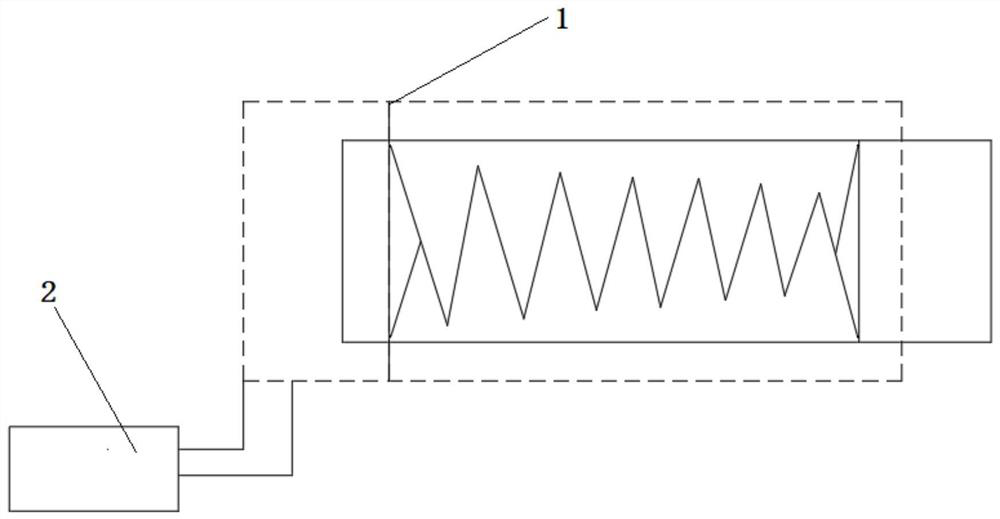
[0043] see figure 1 , a kind of continuous pushing self-moving tail described in a preferred embodiment of the present invention, comprises continuous pushing device 1 and power unit 2,

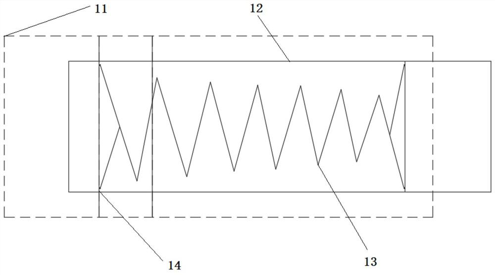
[0044] see figure 2 , the continuous pushing device 1 includes an outer pushing frame device 11, an inner pushing frame device 12, a flexible telescopic device 13, and a pin shaft 14, and the outer pushing frame device 11 is movable across the inner moving frame through a misalignment groove On the surface of the device 12, the outer push frame device 11 and the inner push frame device 12 are on the same horizontal plane; the left and right sides of the flexible telescopic device 13 ar...


PUM


Abstract

The invention relates to a continuous pushing self-moving machine tail, and belongs to the technical field of coal mine fully-mechanized coal mining and fully-mechanized excavation working face transportation equipment. The continuous pushing self-moving machine tail comprises a continuous pushing device and a power device, wherein the continuous pushing device comprises an outer pushing frame device, an inner pushing frame device, a flexible telescopic device and pin shafts; the left side and the right side of the flexible telescopic device are connected with the outer pushing frame device and the inner pushing frame device through the pin shafts correspondingly; and the outer pushing frame device comprises an outer pushing frame body, a plurality of lifting mechanisms mounted at the bottom of a main beam of the outer pushing frame body, paws fixed to the lower portions of the lifting mechanisms, a left-right guiding mechanism fixed to the outer pushing frame body, and a plurality oflongitudinal guiding mechanisms fixed to the outer pushing frame body. The inner pushing frame device comprises an inner pushing frame body, a plurality of lifting mechanisms mounted at the bottom ofa main beam of the inner pushing frame body, paws fixed to the lower portions of the lifting mechanisms, a left-right guiding mechanism fixed to the inner pushing frame body, and a plurality of longitudinal guiding mechanisms fixed to the inner pushing frame body.

Description

technical field [0001] The invention relates to a continuously moving self-moving machine tail, which belongs to the technical field of transportation equipment for fully mechanized fully mechanized excavation working faces of coal mines. Background technique [0002] At present, the complete set of equipment for the fully mechanized mining face of the coal mine is mainly composed of a shearer, a scraper conveyor, a hydraulic support, a bridge loader, a trough belt, a shifting train, a pump station, a switch, and a substation. [0003] As the main equipment for raw coal transportation, the along-trough belt is initially laid with a long fixed bracket with continuous bottom support. With the recovery of the working face, the along-trough belt shrinks accordingly, and the fixed bracket at the bottom of the belt is quantitatively removed. [0004] Due to the limitation of the geological conditions of the tunnel roadway, it is not realistic to realize the long-distance mining fa...

Claims


Application Information

Patent Timeline
Patent Type & Authority Applications(China)
IPC IPC(8): B65G15/64B65G15/00B65G21/14B65G41/00B65G39/16E21F13/06
CPCB65G15/00B65G15/64B65G21/14B65G39/16B65G41/001E21F13/06
Inventor 杨庆丰朱贤圣陈利剑冯鹃王建伟张仲元林冬伟付玉松肖晨光
Owner CHANGZHOU LIANLI AUTOMATION TECH
Why Eureka
Try Eureka