
A feeding device for cleaning aluminum rods

A technology of feeding device and aluminum bar, applied in the directions of cleaning methods and utensils, transportation and packaging, chemical instruments and methods, etc., can solve the problems of laborious handling by workers, inconvenient transportation of aluminum bars, high labor cost, and achieve convenient cleaning, The effect of reducing labor intensity and saving labor costs

Active Publication Date: 2021-10-12
重庆恒亚实业有限公司
View PDF6 Cites 0 Cited by
  • Summary
  • Abstract
  • Description
  • Claims
  • Application Information

AI Technical Summary

Problems solved by technology

[0006] The purpose of the present invention is to provide a feeding device for cleaning aluminum rods, which can transport the aluminum rods from the feeding chute to the two rollers of the conveying equipment through the conveyor belt and the material receiving plate, and solve the problem of when the aluminum rods are transported. , a cleaning equipment needs to be equipped with a separate worker to carry the aluminum rods upwards one by one. The workers' handling is more laborious, the labor cost is high, and the transportation of the aluminum rods is inconvenient, so that the workers do not need to directly carry the aluminum rods, saving Employee physical strength, one person can operate multiple devices at the same time, the labor cost is reduced, and the purpose of facilitating the transportation of aluminum rods

Method used


Image

  • A feeding device for cleaning aluminum rods
  • A feeding device for cleaning aluminum rods
  • A feeding device for cleaning aluminum rods

Examples


Embodiment Construction

[0036] The implementation of the present application will be described in detail below with reference to the accompanying drawings and examples, so as to fully understand and implement the implementation process of how the present application uses technical means to solve technical problems and achieve technical effects.

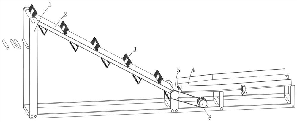
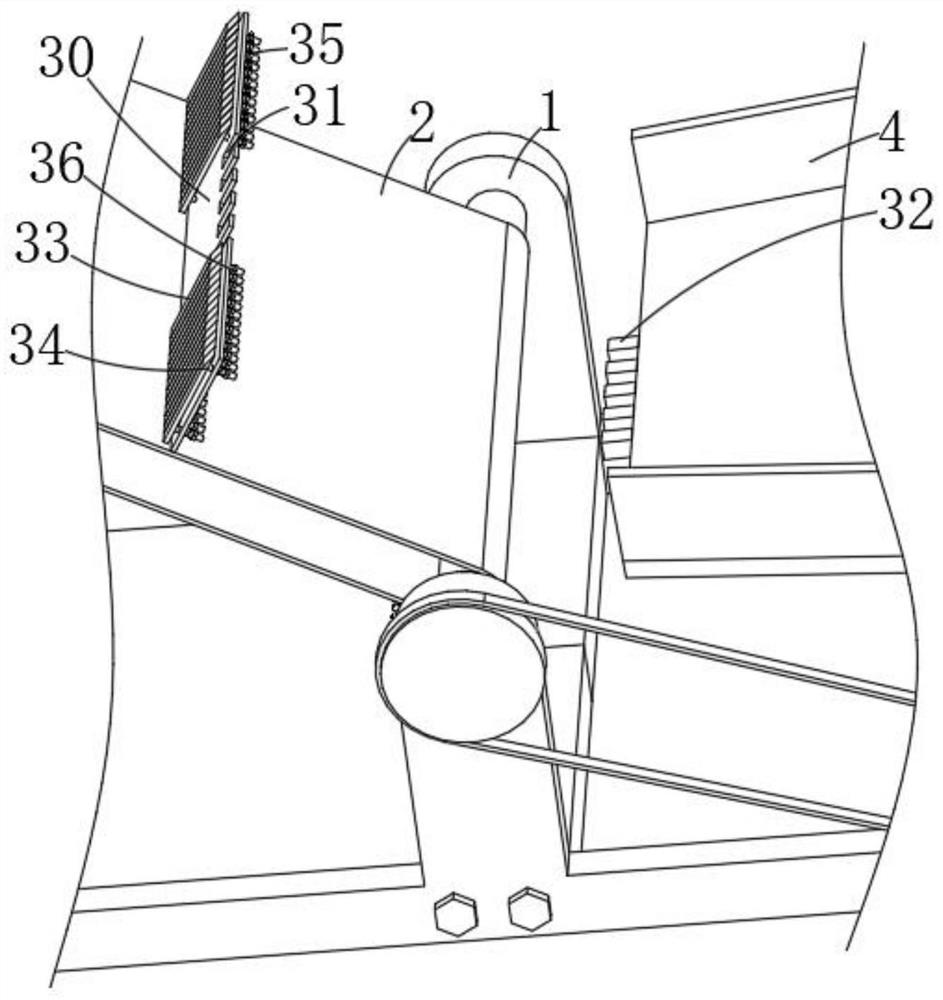
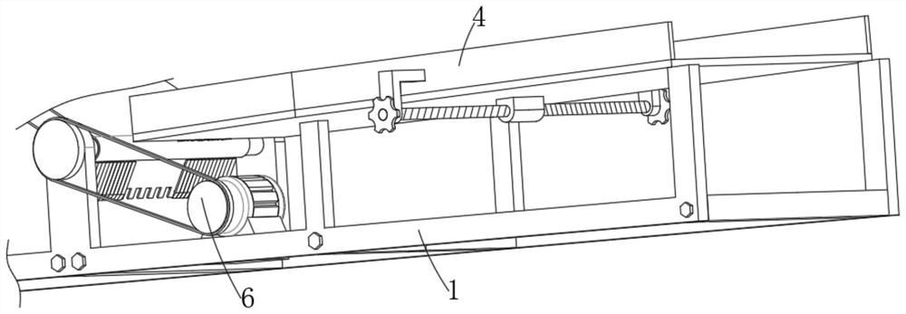
[0037] like figure 1 , figure 2 and image 3 Shown, embodiment one, the present invention provides a kind of feeding device for cleaning aluminum rods, comprising,

[0038] Rack 1, installed on the ground;

[0039] Conveyor belt 2, the conveyor belt 2 is installed on the frame 1 through the rotating roller, and the pulley of the conveyor belt 2 is connected to the frame 1 through the rotating roller;

[0040] The material receiving assembly 3 is fixed on the surface of the conveyor belt 2 at equal intervals along the conveying direction of the conveyor belt 2. The material receiving assembly 3 is fixedly connected with the conveyor belt 2, and the materi...


PUM


Abstract

The invention relates to the technical field of aluminum bar processing, in particular to a feeding device for cleaning aluminum bars, comprising: a frame, which is installed on the ground; a conveyor belt, which is installed on the frame through rotating rollers; a material receiving assembly, which is conveyed along the conveyor belt The direction is fixed on the surface of the conveyor belt at equal intervals; the feeding chute is installed on the frame and located on the feeding side of the conveyor belt. The width is larger than the radius of the aluminum rod and smaller than the diameter of the aluminum rod. When the conveyor belt conveys the material receiving component through the discharge end of the feeding chute, the material receiving component takes away the aluminum rod in the material storage gap; the power component is installed in the rack superior. The invention only needs to place full aluminum rods on the guide plate at a time, and only needs to add aluminum rods once after a period of time to ensure automatic feeding of aluminum rods, reduce labor intensity, and one employee can operate multiple cleaning equipment at the same time. , save labor costs, and the cleaning of aluminum rods is more convenient.

Description

technical field [0001] The invention relates to the technical field of aluminum rod processing, in particular to a feeding device for cleaning aluminum rods. Background technique [0002] Aluminum rod is a kind of aluminum product. The melting and casting of aluminum rod includes melting, purification, impurity removal, degassing, slag removal and casting process. When aluminum rod is processed into aluminum rod, it needs to be cleaned, dried, heated and In ring cutting and other processes, when cleaning aluminum rods, the aluminum rods are mostly transported into the cleaning liquid through conveying equipment, and cleaned by ultrasonic vibration. [0003] In the aluminum rod cleaning equipment, the aluminum rod is limited by two parallel rollers connected to the chain. The aluminum rod and the two parallel rollers are in a parallel state. The two rollers carry the aluminum rod into the cleaning pool. The front end of the conveying equipment is located above the cleaning l...

Claims


Application Information

Patent Timeline
Patent Type & Authority Patents(China)
IPC IPC(8): B65G23/04B65G15/44B65G23/22B65G47/34B08B13/00
CPCB08B13/00B65G15/44B65G23/04B65G23/22B65G47/34B65G2201/0217
Inventor 陈明佐陈雨
Owner 重庆恒亚实业有限公司
Learn More