
Frame type roadbed retaining structure

A technology of supporting structure and frame structure, which is applied in basic structure engineering, underwater structure, building structure, etc., can solve the difficulty of forming anchor cable holes, high construction safety risks, and the lack of research and specification of ordinary roadbed retaining walls. Perfect and other problems, to achieve reliable anti-falling rock performance, reduce construction difficulty and risk, and achieve the effect of adding value to the project

Pending Publication Date: 2020-10-30
CMCU ENG
View PDF0 Cites 3 Cited by
  • Summary
  • Abstract
  • Description
  • Claims
  • Application Information

AI Technical Summary

Problems solved by technology

[0006] 1. It is difficult for the anti-slide pile with rectangular cross-section to form holes in the deep soil layer in mountainous areas, and the construction safety risk is great
[0007] 2. The traditional double-row pile structure is set on one side of the road, far beyond the red line of the road, and occupies a large area
[0008] 3. For the anchor pile structure, it is difficult for the anchor cable to form a hole in the deep soil layer, and for the slope with a certain deformation in the later stage, it is easy to cause many problems with the anchor cable
[0009] 4. When there is a possibility of falling rocks on the mountain, the ordinary roadbed support structure has no anti-fall function
[0010] 5. It is difficult to give full play to the seismic performance of ordinary subgrade retaining walls due to imperfect related research and specifications
[0011] 6 After excavating road cuttings, the hillside green space is artificially divided, destroying the original function of urban mountain greening

Method used


Image

  • Frame type roadbed retaining structure
  • Frame type roadbed retaining structure
  • Frame type roadbed retaining structure

Examples


Embodiment

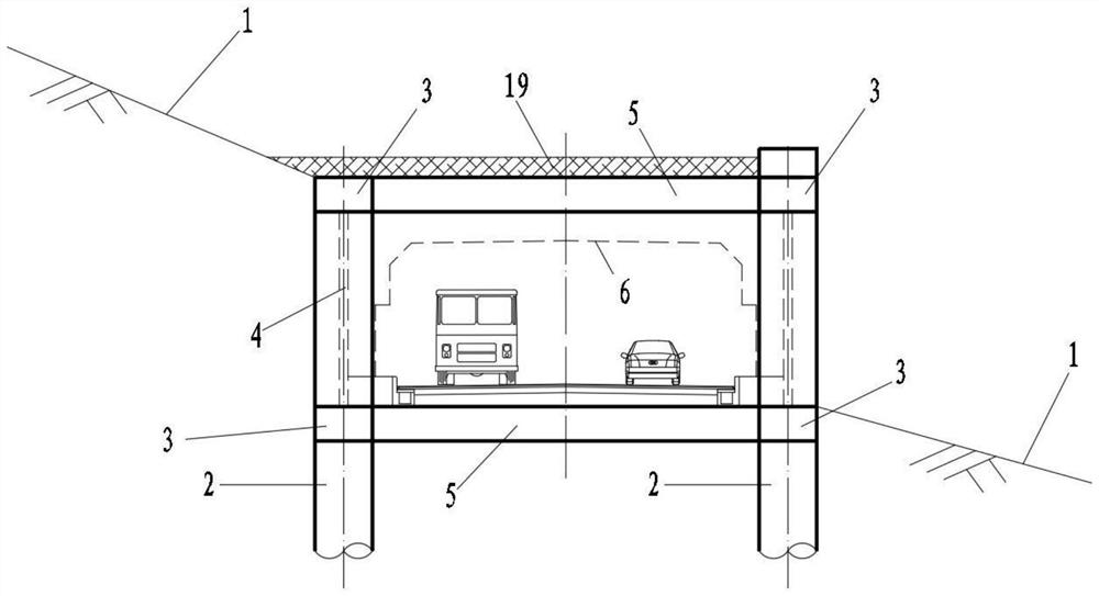
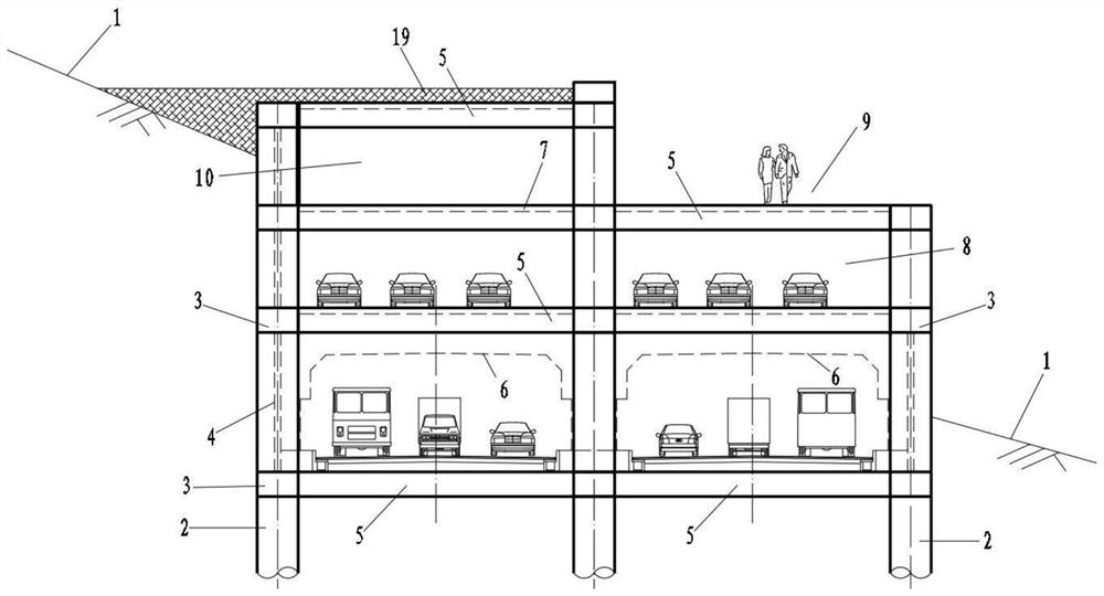
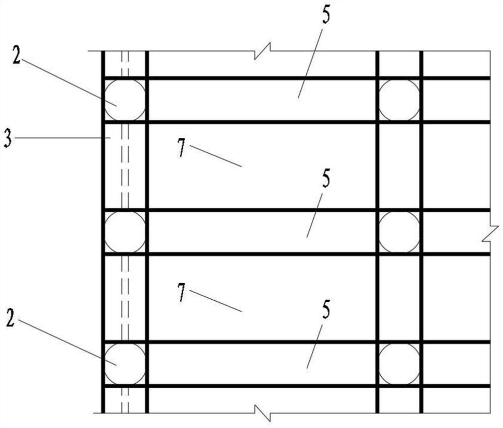
[0053] The utility model relates to a frame-type subgrade support structure, which is a multi-layered frame structure. Such as Figure 6 Shown: The road building boundary 6 is located in the middle of the mountain slope 1. The residual fill soil on the slope surface is formed by urban construction, and the thickness of the fill soil is 20-30m. The current situation is the green area of ​​the mountain park, with the underlying bedrock. After the road cutting is excavated, the upper slope of the road will slide, and the sliding force of the landslide is converted to the anti-slide piles, which are distributed according to a rectangle, and the load of the landslide body 16 that each pile bears is 400KN / m. According to the layout of the road width, four rows of anti-slide piles with circular cross-section are used to support the block. The anti-slide piles 2 need to be embedded below the soil-rock boundary line 11, and the anti-slide piles 2 are preferably embedded 9m to 10m below...


PUM


Abstract

The invention relates to a frame type roadbed retaining structure, and belongs to the technical field of geotechnical engineering and structural engineering. The frame type roadbed retaining structurecomprises a frame structure, wherein the frame structure comprises single-row anti-slide piles arranged on two sides of a road, longitudinal frame beams arranged in the extending direction of the road and connected with the anti-slide piles, and transverse frame beams arranged in the width direction of the road and connected with the anti-slide piles; the transverse frame beams comprise a top transverse frame beam positioned on the top of the road and a bottom transverse frame beam positioned below the road surface; a soil retaining plate and a floor are respectively arranged on two sides andthe top of the frame structure; and a falling stone impact preventing buffer layer is arranged on the floor positioned on the top of the frame structure. The frame type roadbed retaining structure can be used for a semi-excavation roadbed slope, can also be used for a full-excavation cutting slope, and mainly solves the influence of bearing of higher lateral soil pressure, landslide thrust and hillside falling stone impact load on the road.

Description

technical field [0001] The invention belongs to the technical field of geotechnical engineering and structural engineering, and relates to a frame-type subgrade retaining structure, which can be used as a retaining structure for excavated subgrade slopes, and can also be used as a shed-cave structure for roads on mountain slopes. Background technique [0002] There are many mountainous towns in the western region of my country. Due to the limited land use conditions in these cities, many buildings, roads and public facilities need to be built on mountain slopes. [0003] For the road excavation subgrade set on the mountain, when there is a deep and unstable soil layer or other conditions that generate large sliding force and earth pressure, it is difficult for the traditional retaining structure to meet the needs of supporting the slope. [0004] Traditional retaining structures generally adopt two forms of double-row piles and anchor-stayed pile-slab retaining walls. In ad...

Claims


Application Information

Patent Timeline
IPC IPC(8): E04H14/00E01F7/04E02D5/22E02D29/02
CPCE01F7/04E02D5/22E02D29/02E04H14/00
Inventor 幸芊张勇洪兆远
Owner CMCU ENG
Learn More