
Water-cooled multi-split heat recovery floor heating device

A multi-connection, heat recovery technology, applied in hot water central heating systems, household heating, heating methods, etc., can solve the problems of radiation source heat reduction, temperature difference, energy waste, etc. Effects of high radiation levels and high ambient temperature

Active Publication Date: 2020-10-30
江苏西墅新能源科技有限公司
View PDF22 Cites 0 Cited by
  • Summary
  • Abstract
  • Description
  • Claims
  • Application Information

AI Technical Summary

Problems solved by technology

[0002] Underfloor heating uses the whole ground as a radiator, heats the entire ground evenly through the heat medium in the radiant layer of the floor, and supplies heat to the room through the ground in a radiant manner to achieve the purpose of comfortable heating. During the use of floor heating, the radiant layer Heating is to heat up the whole house by heat radiation. However, under special circumstances, people do not often move around all the rooms. For example, they only stay in the bedroom when they sleep at night, and when they are not at home when they go out, this will cause energy waste. Moreover, the air supply and liquid supply radiant floor heating will flow with the pipeline, so that the heat of the radiation source will gradually decrease, which will cause a phenomenon of temperature difference in the space, and it cannot guarantee that every corner can achieve comfortable floor heating. In the existing gas-liquid radiation heating environment, a large amount of heat energy will be lost, and the lost heat energy cannot be effectively recycled, so people need a water-cooled multi-connected heat recovery floor heating device to solve the above problems

Method used


Image

  • Water-cooled multi-split heat recovery floor heating device
  • Water-cooled multi-split heat recovery floor heating device
  • Water-cooled multi-split heat recovery floor heating device

Examples


Embodiment

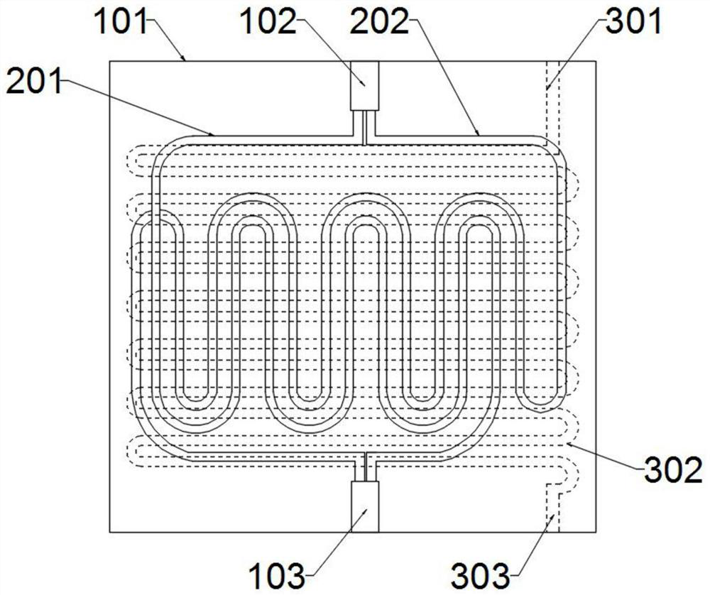
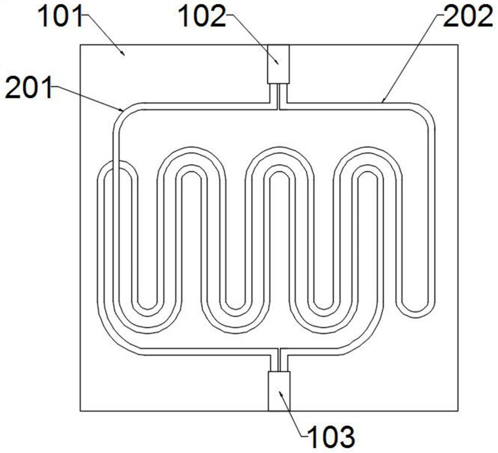
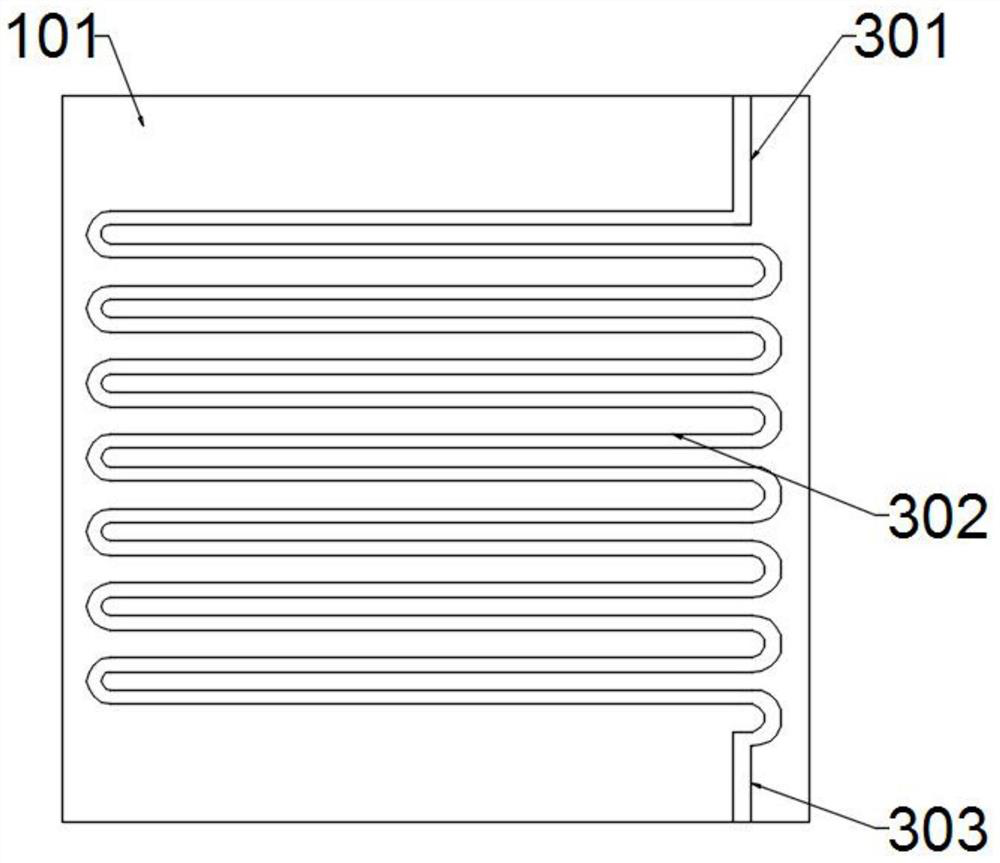
[0027] Example: such as Figure 1~6 As shown, the water-cooled multi-connected heat recovery floor heating device includes a basic support component, a heat compensation component, a heat absorption component, an air intake component, an exhaust component, and a water flow drive component. The role of other components in the support device. The basic support component is equipped with a thermal compensation component. The thermal compensation component plays the role of compensating and balancing the regional temperature difference of the heating. There is a heat absorption component under the thermal compensation component. The heat absorption component plays a timely role. The function of absorbing heating heat for energy storage, the side of the thermal compensation component is provided with an air intake component, and the intake component plays the role of distributing the intake air into the thermal compensation component, and the end of the thermal compensation componen...


PUM


Abstract

The invention discloses a water-cooled multi-split heat recovery floor heating device, and belongs to the technical field of floor heating type heat supply. The device comprises a base support assembly, a thermal compensation assembly and a heat absorbing assembly, wherein the base support assembly is located at the bottommost end of the entire set of the device, the base support assembly is internally provided with the thermal compensation assembly, and the heat absorbing assembly is arranged below the thermal compensation assembly. The device is scientific and rational and safe and convenient in use, in a special environment in the use process of the floor heated air, people do not move in all the rooms frequently, so that energy waste is caused, the device adopts a plurality of mountinggroove plates to carry out splicing type regional thermal radiation, the whole house can obtain uniform thermal radiation, and the splicing type heat supply effect enables each mounting groove plateto close an air circuit separately to realize scientific distribution and utilization of the heated air; and a PLC controls a valve, and the heat is only supplied to the environment requiring the heated air, so that the energy consumption is greatly saved on.

Description

technical field [0001] The invention relates to the technical field of floor heating and heating, in particular to a water-cooled multi-connection heat recovery floor heating device. Background technique [0002] Underfloor heating uses the whole ground as a radiator, heats the entire ground evenly through the heat medium in the radiant layer of the floor, and supplies heat to the room through the ground in a radiant manner to achieve the purpose of comfortable heating. During the use of floor heating, the radiant layer Heating is to heat up the whole house by heat radiation. However, under special circumstances, people do not often move around all the rooms. For example, they only stay in the bedroom when they sleep at night, and when they are not at home when they go out, this will cause energy waste. Moreover, the air supply and liquid supply radiant floor heating will flow with the pipeline, so that the heat of the radiation source will gradually decrease, which will cau...

Claims


Application Information

Patent Timeline
Patent Type & Authority Applications(China)
IPC IPC(8): F24D3/10F24D3/14F24D19/10
CPCF24D3/146F24D3/1075F24D19/1015
Inventor 叶余良叶璇肖华
Owner 江苏西墅新能源科技有限公司
Learn More