Method and reactor for pyrolysis conversion of hydrocarbon gases

A pyrolysis reactor, the technology of the reactor, is applied in the directions of pyrolysis reaction, gas-gas reaction at high temperature, chemical instruments and methods, etc., and can solve problems such as heat loss

Active Publication Date: 2020-10-30
SABIC GLOBAL TECH BV
View PDF15 Cites 2 Cited by
  • Summary
  • Abstract
  • Description
  • Claims
  • Application Information

AI Technical Summary

Problems solved by technology

The main disadvantage of this type of design is the large heat loss that results when cooling the burner walls to protect them

Method used


Image

  • Method and reactor for pyrolysis conversion of hydrocarbon gases
  • Method and reactor for pyrolysis conversion of hydrocarbon gases
  • Method and reactor for pyrolysis conversion of hydrocarbon gases

Examples


Embodiment 1

[0091] Image 6 The pyrolysis reactor geometry and axial velocity distribution in a laboratory-scale unit model are shown. The direction of the area arrow indicates the flow direction of the gas phase, and its length indicates the relative magnitude of the velocity. At the inlet of the feed assembly, for O 2 and CH 4 , the axial velocity is zero, the radial velocity is consistent with the azimuth velocity, and the azimuth-radial velocity ratio is 3. This highly swirling flow forms a recirculation zone near the axis of the reactor, as above in Figure 5 As described in , this recirculation zone stabilizes the flame and enhances mixing during combustion. The reflux (close to Image 6 The counterflow area of ​​the axis in the middle) presses the combustion towards the nozzle neck. This can be found at Figure 7 , where the darker areas downstream of the burner duct indicate higher temperatures, while the lighter areas indicate lower temperatures. The backflow of the gas p...

Embodiment 2

[0097] Figure 12 Two inlet streams are shown (CH 4 and O 2 ) combined effect of the azimuth-radial velocity ratio. The co-rotation of the two streams at a high azimuthal-to-radial velocity ratio of 3 achieves peak yields, suggesting that a high azimuthal-to-radial velocity ratio is beneficial for creating a wide recirculation zone and rapid mixing.

Embodiment 3

[0099] Figure 13 The effect of the methane / oxygen molar ratio on pyrolysis performance is shown, the ratio varying from 1.6 to 2.4. Sensitivity analyzes indicated that overall methane conversion decreases with increasing methane / oxygen ratio due to combustion temperature and thermal energy available for pyrolysis. On the other hand, the selectivity increased slightly, from a ratio of 1.6 to a ratio of about 2. As the product of these two indicators, under specific operating conditions, the overall C 2 + Yield peaks at a ratio of about 1.8, reaching about 28.2% at this particular scale. It is worth noting that the optimized methane / oxygen ratio may vary under different reactor sizes, heat losses, and operating pressures.


PUM


Abstract

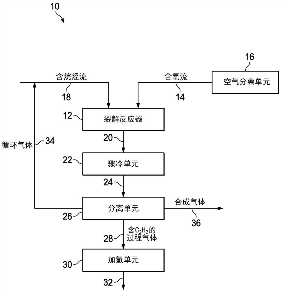
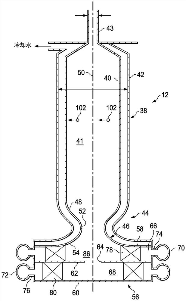
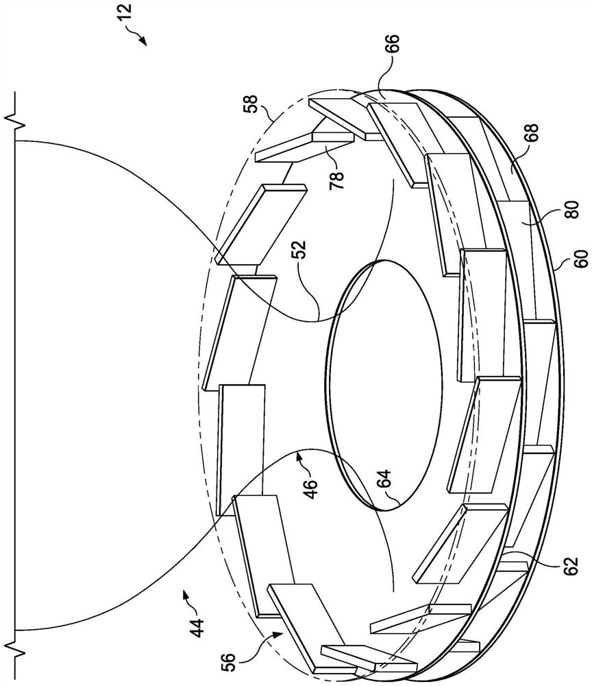
A pyrolysis reactor (12) and a method for the pyrolysis of hydrocarbon gases (e.g., methane) are provided. The method utilizes a pyrolysis reactor (12) having a unique burner assembly (44) and a pyrolysis feed assembly (56) that creates an inwardly spiraling fluid flow pattern of the feed gases to form a swirling gas mixture that passes through a burner conduit (46) with a constricted neck portionor nozzle (52). At least a portion of the swirling gas mixture forms a thin, annular mixed gas flow layer immediately adjacent to the burner conduit (46). A portion of the swirling gas mixture is combusted as the swirling gas mixture passes through the burner conduit (46) and a portion of combustion products circulates in the burner assembly (44). This provides conditions suitable for pyrolysis of hydrocarbons or light alkane gas, such as methane or natural gas.

Description

technical field [0001] The present invention relates to a process for the conversion of hydrocarbons, especially alkanes, to the pyrolysis products of this conversion and to a reactor design for this conversion. Background technique [0002] There are many conventional methods for converting lower molecular weight carbon-containing molecules to higher molecular weight. The most common methods involve oxidative coupling, partial oxidation or pyrolysis. Each method has its own advantages and challenges. High temperature pyrolysis of methane is commonly used for the commercial production of acetylene. Pyrolysis of methane and / or hydrocarbons to acetylene is broadly classified as a one-stage process or a two-stage process, depending on the method used to supply the endothermic heat required for pyrolysis. [0003] The single-stage process produces acetylene primarily through the partial oxidation of methane. A representative single-stage process is that developed by BASF Cor...

Claims


Application Information

Patent Timeline
Patent Type & Authority Applications(China)
IPC IPC(8): B01J8/02C07C5/327
CPCB01J6/008C07C2/78C07C11/24B01J4/005B01J12/005B01J19/0053B01J19/02B01J19/2415B01J2204/002B01J2219/00094B01J2219/1943B01J19/2405B01J19/246
Inventor S·潘纳拉V·施特恩L·陈D·韦斯特
Owner SABIC GLOBAL TECH BV
Why Eureka
Try Eureka