Surface treatment device used after rubber tire manufacturing and molding

A technology for rubber tires and processing equipment, used in manufacturing tools, metal processing equipment, grinding/polishing equipment, etc., can solve the problems of environmental sanitation, poor effect, high labor intensity, etc. labor-intensive effect

Active Publication Date: 2020-11-03
江门腾晖橡胶有限公司
View PDF8 Cites 7 Cited by
  • Summary
  • Abstract
  • Description
  • Claims
  • Application Information

AI Technical Summary

Problems solved by technology

[0003] However, the following problems exist in the current rubber tire deburring. 1. When the traditional rubber tire is deburred, it is generally cut manually with a machete, and in the process of removing the rubber burr, it is necessary to constantly adjust its standing position, after one side of the rubber burr is removed, the tire needs to be turned over, and the rubber burr is removed on the other side. Manually removing the rubber tire burr is labor-intensive, the effect is poor, the efficiency is low, and it is easy to cause the tire to fail to meet the standard , so that the qualified rate of tires is reduced; 2. When the existing rubber tire burr removal equipment is removing burrs, the burrs are often removed incompletely, and the removed burrs cannot be collected, which affects environmental sanitation and can reduce the efficiency of rubber tire deburring. and effects

Method used


Image

  • Surface treatment device used after rubber tire manufacturing and molding
  • Surface treatment device used after rubber tire manufacturing and molding
  • Surface treatment device used after rubber tire manufacturing and molding

Examples


Embodiment Construction

[0029] The embodiments of the present invention will be described in detail below with reference to the accompanying drawings, but the present invention can be implemented in many different ways defined and covered by the claims.

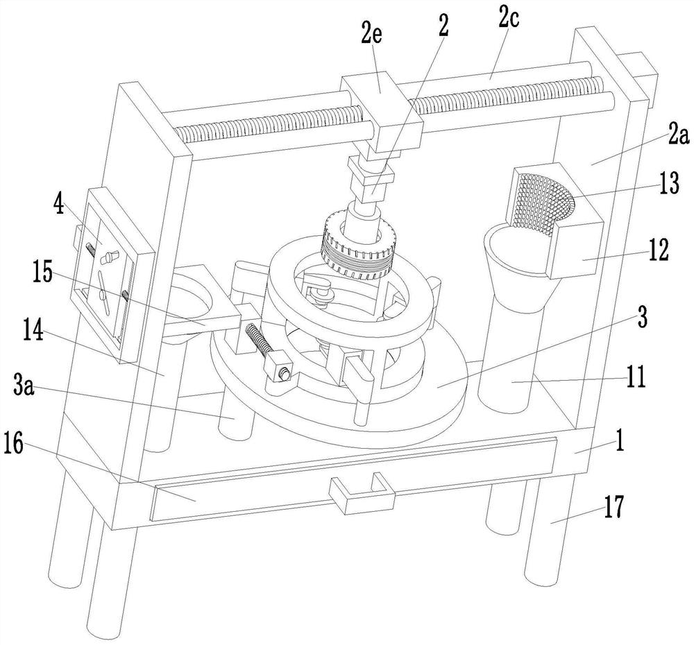
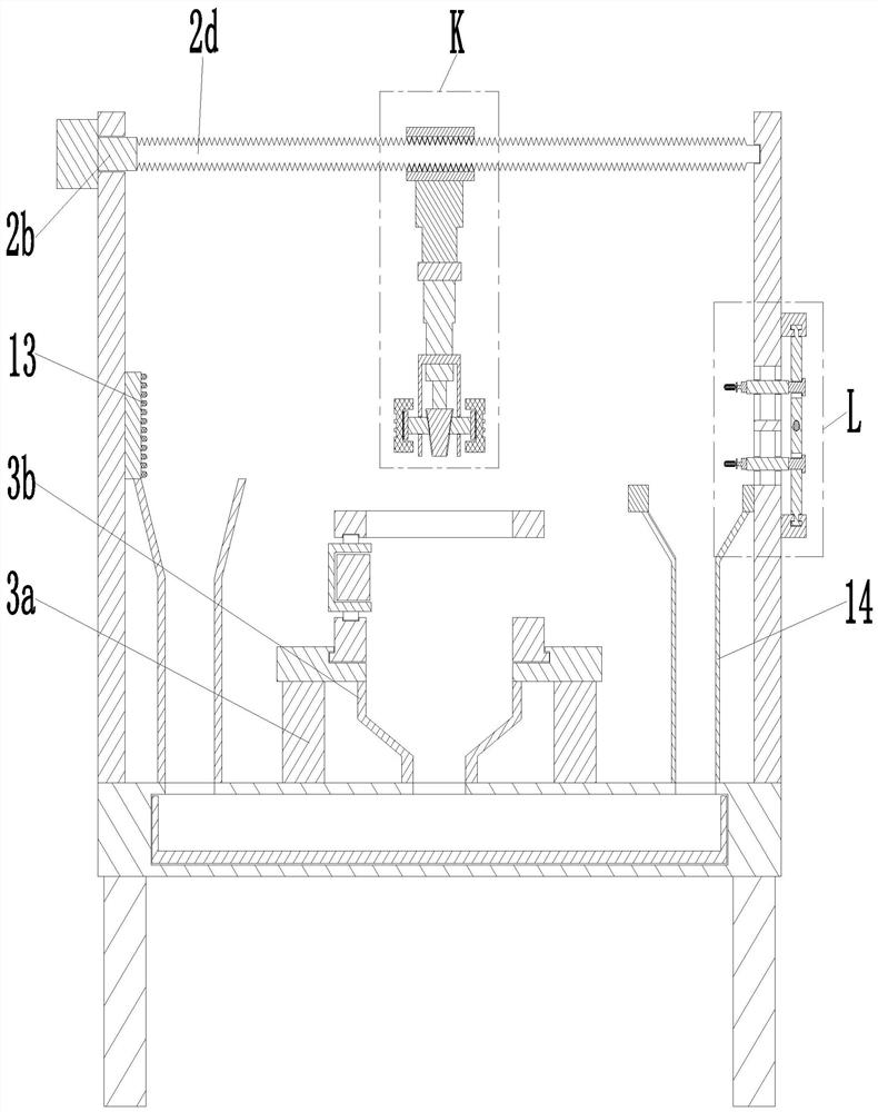
[0030] Such as Figure 1 to Figure 7 As shown, a surface treatment equipment after rubber tire manufacturing and molding includes a base plate 1, a clamping device 2, a grinding device 3 and a grinding device 4. The clamping device 2 is installed on the base plate 1, and the clamping device 2 is A grinding device 4 is installed, and a grinding device 3 is installed at the middle end of the bottom plate 1 .

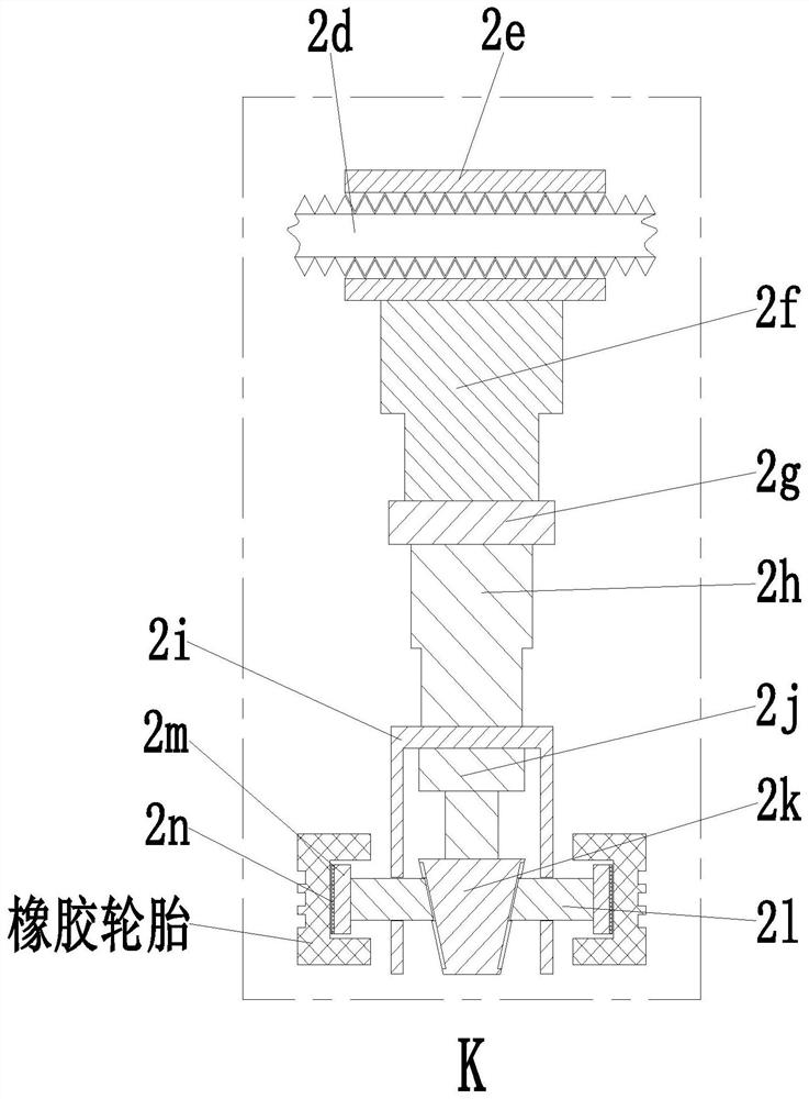
[0031]The clamping device 2 includes a support plate 2a, a No. 2 motor 2b, a sliding round rod 2c, a clamping threaded rod 2d, a square plate 2e, a telescopic cylinder 2f, a clamping plate 2g, a No. 3 motor 2h, and a clamping round rod 2i , clamping cylinder 2j, pressing rod 2k, ejector rod 2l, arc panel 2m and rubber plate 2n, the left and rig...


PUM


Abstract

The invention relates to a surface treatment device used after rubber tire manufacturing and molding. The surface treatment device comprises a bottom plate, a clamping device, a grinding device and agrinding removing device, wherein the clamping device is arranged on the bottom plate, the grinding removing device is arranged on the clamping device, and the grinding device is arranged at the middle end of the bottom plate. The surface treatment device can solve the following problems, existing in a rubber tire burr removing process at present, that 1, in the traditional rubber tire burr removing process, generally, a curved blade is manually held to conduct cutting, in the rubber burr removing process, the standing position of a user needs to be continuously adjusted, after rubber burrs onone side are removed, a tire needs to be turned over to conduct rubber burr removing operation on the other side, and the labor intensity of manual rubber tire burr removing is high; and 2, when burrs are removed through an existing rubber tire burr removing device, incomplete burr removing often occurs, the burrs after removal cannot be collected, the environmental sanitation is affected, and the rubber tire burr removing efficiency and effect can be affected.

Description

technical field [0001] The invention relates to the technical field of rubber tire production and processing, in particular to a surface treatment device after rubber tire manufacturing and molding. Background technique [0002] Rubber tires are usually installed on metal rims, which can support the body, buffer external impact, realize contact with the road surface and ensure the driving performance of the vehicle. Rubber tires are often used under complex and harsh conditions, and they are subjected to various deformations during driving. , load, force, and high and low temperature effects, so it must have high load-carrying performance, traction performance, and cushioning performance. After the tire is manufactured, in order to ensure the quality of the tire, it is necessary to deburr the tire. [0003] However, the following problems exist in the current rubber tire deburring. 1. When the traditional rubber tire is deburred, it is generally cut manually with a machete, ...

Claims


Application Information

Patent Timeline
IPC IPC(8): B24B9/20B24B55/06B24B41/06B24B41/02B24B47/06B24B47/12
CPCB24B9/20B24B55/06B24B41/067B24B41/02B24B47/06B24B47/12
Inventor 未海
Owner 江门腾晖橡胶有限公司
Why Eureka
Try Eureka