Calender for PVC film production

A PVC film, calender technology, applied in the direction of applications, household appliances, other household appliances, etc., to achieve the effect of avoiding breakage

Inactive Publication Date: 2020-11-03
江苏入佳境信息科技有限公司
View PDF0 Cites 1 Cited by
  • Summary
  • Abstract
  • Description
  • Claims
  • Application Information

AI Technical Summary

Problems solved by technology

The pressure rollers of the traditional calender are all cylindrical, but during the calendering process of PVC film, the film will spread from the middle to both sides, resulting in the production of PVC film with a thin middle and thick sides, which cannot meet people's needs.

Method used


Image

  • Calender for PVC film production
  • Calender for PVC film production
  • Calender for PVC film production

Examples


Embodiment 1

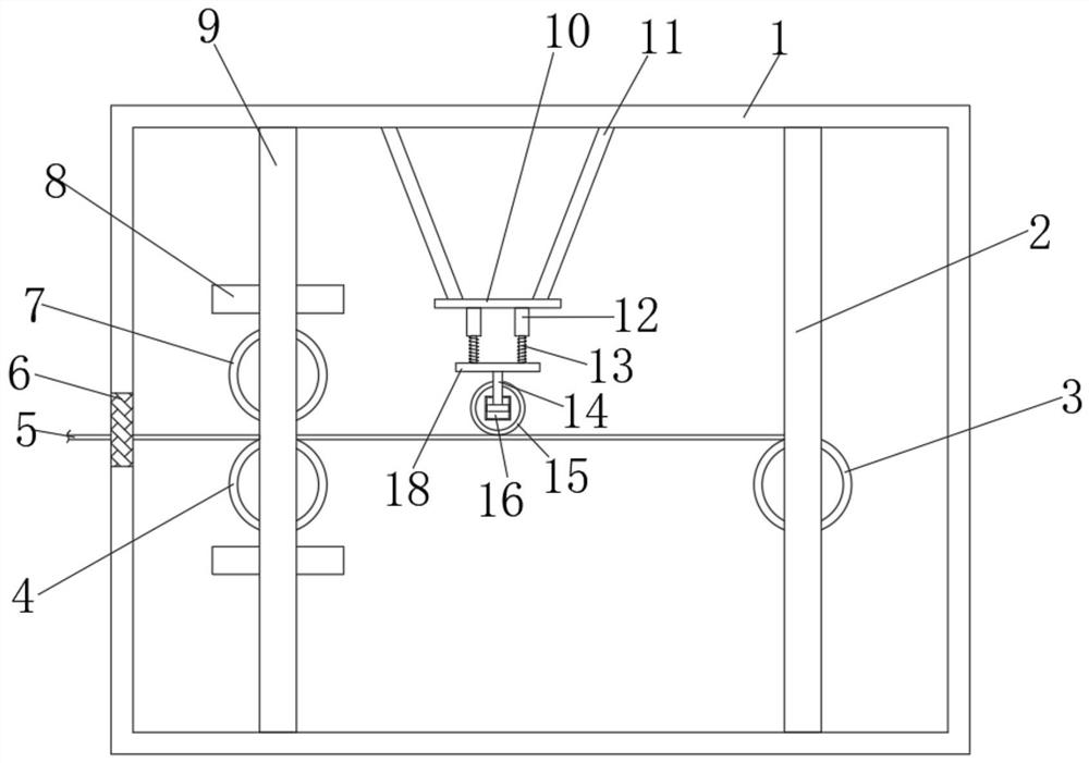
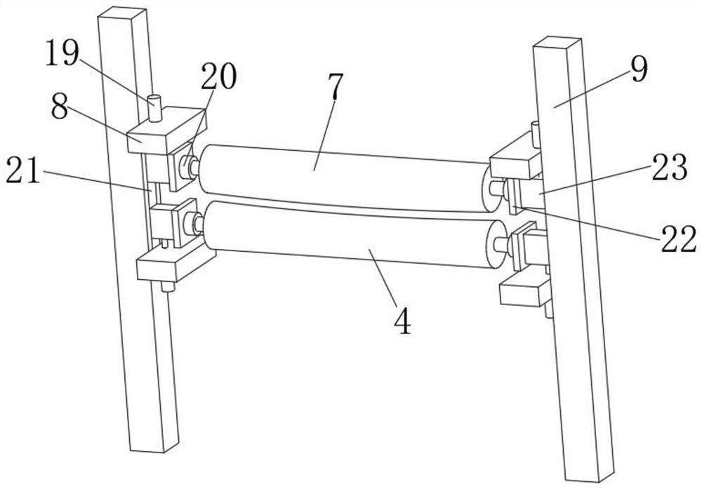
[0028] refer to Figure 1-3 , a calender for PVC film production, comprising a box body 1, the top and bottom inner walls of the box body 1 are connected with a second fixed rod 9 by bolts, and one side outer wall of the second fixed rod 9 is connected with a first fixed rod by bolts. Connecting plate 8, the top outer wall of the first connecting plate 8 is plugged with an electric push rod 19, and one end outer wall of the electric push rod 19 is connected with a slider 23 by bolts, and one side outer wall of the second fixed rod 9 has a chute 21 , and the slider 23 forms a sliding connection with the chute 21, the outer wall on one side of the slider 23 is connected with the third connecting plate 22 by bolts, and the outer wall on one side of the third connecting plate 22 is connected with the bearing seat 20 by bolts, the bearing seat The inner wall of one side of 20 is rotatably connected with the second pressure roller 7, and the inner wall of one side of the other beari...

Embodiment 2

[0032] refer to Figure 4-5 , a calender for PVC film production. Compared with Embodiment 1, the outer wall of one side of the box body 1 is connected with a blower 24 by bolts, and the outer wall of one side of the blower 24 is plugged with an air inlet pipe 25. One end of the air duct 25 extends to the inside of the box body 1, the top outer wall of the air inlet duct 25 is plugged with a connecting pipe 26, and one end of the connecting pipe 26 is plugged with an air outlet nozzle 27, and the cross section of the air outlet nozzle 27 is a whistle. type.

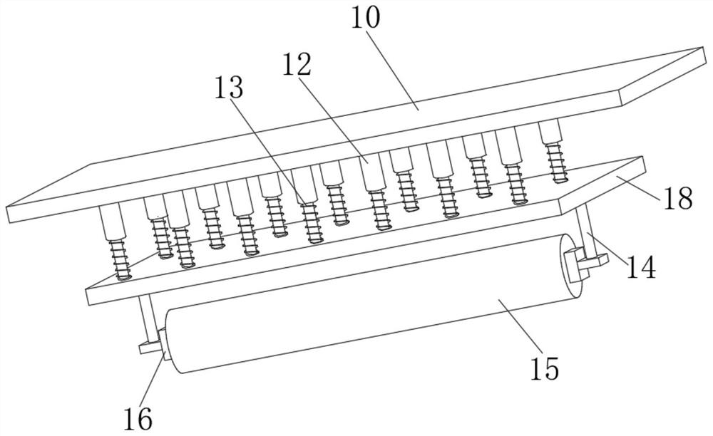
[0033] Working principle: when in use, when people are calendering the PVC film, they can start the electric push rod 19, and the electric push rod 19 drives the first pressure roller 4 and the second pressure roller 7 to move relative or opposite to each other, thereby adjusting the PVC film. The magnitude of the pressure can adjust the calendering degree of the PVC film. At the same time, the top cross section of the f...


PUM


Abstract

The invention discloses a calender for PVC film production. The calender comprises a box body, second fixing rods are arranged on the inner walls of the top and the bottom of the box body correspondingly, a first connecting plate is arranged on the outer wall of one side of each second fixing rod, an electric push rod is inserted into the outer wall of the top of each first connecting plate, and asliding block is arranged on the outer wall of one end of each electric push rod; and a sliding groove is formed in the outer wall of one side of each second fixing rod. According to the calender, when people carry out calendering work on a PVC film, the electric push rods can be started, the electric push rods drive first pressing rollers and second pressing rollers to do face-to-face or back-to-back movement so as to adjust the pressure borne by the PVC film, and the calendering degree of the PVC film can be adjusted; and meanwhile, the cross sections of the tops of the first pressing rollers are in arc shapes, the cross sections of the bottoms of the first pressing rollers are linear, the radian of the arc shapes ranges from 1 degree to 5 degrees, and the situation that in the calendering process of the PVC film, the PVC film diffuses from the middle to the two sides, and consequently the middle of the PVC film is thin and the two sides of the PVC film are thick can be avoided.

Description

technical field [0001] The invention relates to the technical field of PVC film production, in particular to a calender for PVC film production. Background technique [0002] The main component of PVC film is polyvinyl chloride, and other components are added to enhance its heat resistance, toughness, ductility, etc. The top layer of this surface film is lacquer, the main component in the middle is polyvinyl chloride, and the bottom layer is back-coated adhesive. [0003] The calender is composed of two or more rollers arranged in a certain form. At a certain temperature, the rubber or plastic is pressed and stretched into a film with a certain thickness and surface shape, and the fiber cord canvas or steel cord can be processed. Glue-hanging machinery. The calender is one of the essential equipment in the process of PVC film production. The pressure rollers of traditional calenders are all cylindrical, but during the calendering process of PVC film, the film will spread ...

Claims


Application Information

Patent Timeline
Patent Type & Authority Applications(China)
IPC IPC(8): B29C43/24B29C43/32B29C43/58B29L7/00
CPCB29C43/24B29C43/245B29C43/32B29L2007/002
Inventor 李佩佩
Owner 江苏入佳境信息科技有限公司
Why Eureka
Try Eureka