Fuel injection valve and diesel engine

A fuel injection valve and fuel injector technology, which is applied in fuel injection devices, engine components, machines/engines, etc., can solve the problems of multiple injections and precise control of fuel volume, large impact on the sealing cone surface, and static fuel leakage. To avoid problems such as large fuel consumption, achieve the effects of shortened closing delay time, rapid pressure drop, and low static fuel leakage

Active Publication Date: 2020-11-03
FAW JIEFANG AUTOMOTIVE CO
View PDF5 Cites 0 Cited by
  • Summary
  • Abstract
  • Description
  • Claims
  • Application Information

AI Technical Summary

Problems solved by technology

[0003] In the existing fuel injection valve, there is only one oil outlet orifice and an oil inlet orifice, and the flow rate of the oil inlet orifice should be smaller than the oil outlet orifice flow, so as to realize the control of the opening and closing of the needle valve. However, due to the The throttling effect of the oil orifice on the high-pressure oil, the oil inlet speed is slow, and it takes a long time for the high-pressure oil to fill the control chamber through the oil inlet orifice after the injection, which leads to too much delay in the closing of the needle valve. Large, slow response, unable to meet the needs of multiple injections and precise control of oil volume
[0004] In order to solve this technical problem, a fuel injection valve is proposed in the prior art, which adopts a two-position three-way control valve structure. This structure realizes the oil discharge of the oil outlet orifice at the time of fuel injection through the control valve, The function of injecting oil in the opposite direction when oiling realizes one hole for dual purposes and improves the closing speed of the needle valve. However, the structure of the injection valve is complicated, and it is difficult to process and assemble, and there are many coupling parts in it, and the static leakage of fuel in actual work The volume is large, and long-term work has a greater impact on the sealing cone surface in contact with the throttle orifice and the ball valve, and cavitation is prone to occur at the sealing cone surface

Method used


Image

  • Fuel injection valve and diesel engine
  • Fuel injection valve and diesel engine
  • Fuel injection valve and diesel engine

Examples


Embodiment Construction

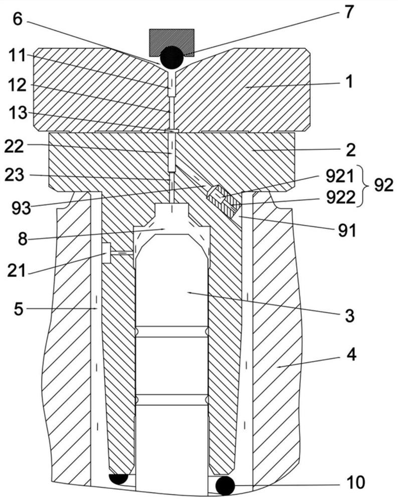
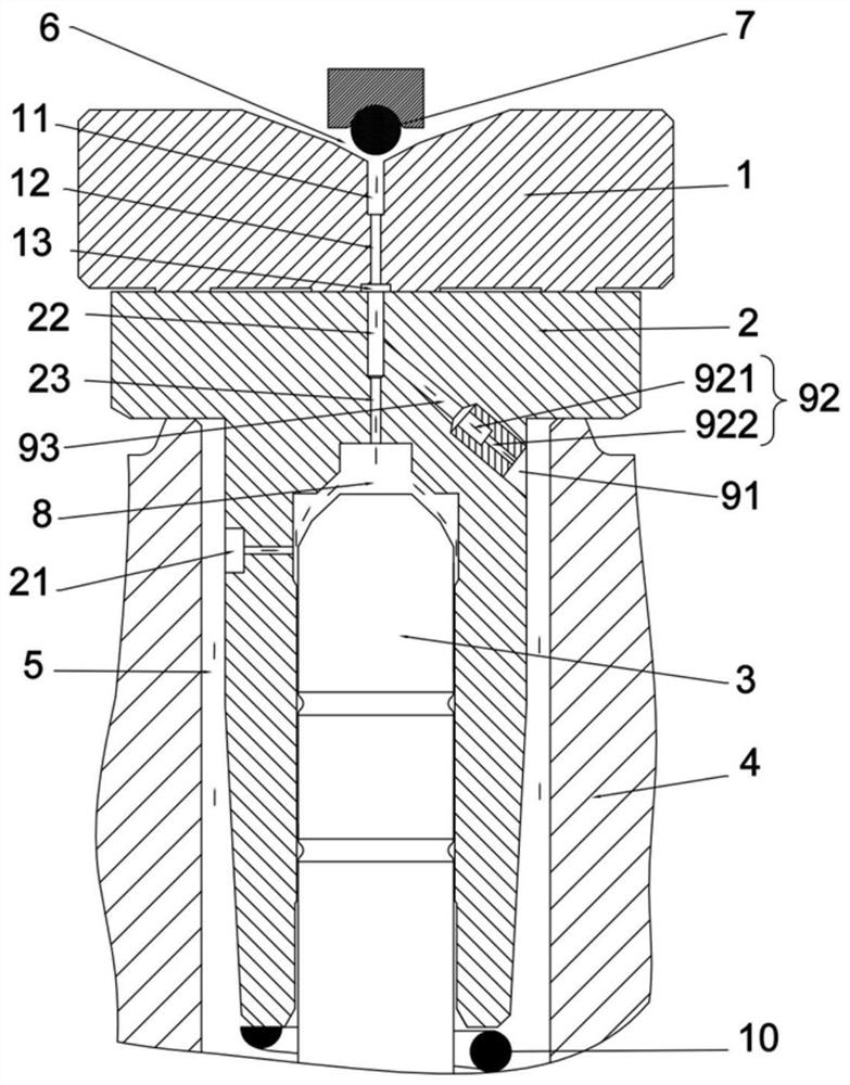
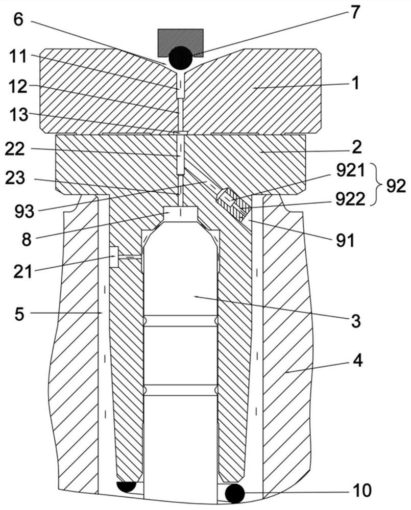
[0046]In order to make the technical problems solved by the present invention, the technical solutions adopted and the technical effects achieved clearer, the technical solutions of the present invention will be further described below in conjunction with the accompanying drawings and through specific implementation methods. It should be understood that the specific embodiments described here are only used to explain the present invention, but not to limit the present invention. In addition, it should be noted that, for the convenience of description, only the parts related to the present invention are shown in the drawings but not all of them.

[0047] In the description of the present invention, unless otherwise clearly specified and limited, the terms "connected", "connected" and "fixed" should be understood in a broad sense, for example, it can be a fixed connection, a detachable connection, or an integrated ; It can be a mechanical connection or an electrical connection; ...


PUM


Abstract

The invention discloses a fuel injection valve and a diesel engine, and belongs to the field of engine fuel injection valves. A control valve sleeve of the fuel injection valve is provided with an oiloutlet passage, and a throttle orifice plate is provided with a low-pressure oil passage, so that the cavitation risk of a sealing conical surface at the top of the throttle orifice plate is favorably reduced; a first throttling ring belt and a second throttling ring belt are successively formed between a long needle valve and the inner wall of the control valve sleeve in the ascending process ofthe long needle valve, the area of the first throttling ring belt and the area of the second throttling ring belt are gradually increased along with ascending of the long needle valve, and the firstthrottling ring belt and the second throttling ring belt jointly play a throttling role, so that the flow of high-pressure oil flowing into a control cavity from an oil inlet hole is rapidly reduced,the pressure of the control cavity is rapidly reduced, and the opening delay is shortened; and the area of the first throttling ring belt and the area of the second throttling ring belt are graduallydecreased along with descending of the long needle valve, the flow of the high-pressure oil flowing into the control cavity from the oil inlet hole is gradually increased, pressure in the control cavity is rapidly established, the closing speed of the long needle valve is increased, and the closing delay time is shortened.

Description

technical field [0001] The invention relates to the technical field of engine fuel injection valves, in particular to a fuel injection valve and a diesel engine. Background technique [0002] In order to meet the increasingly stringent emission requirements, fuel injection valves, which have an important impact on diesel engine emissions, need to further improve their injection accuracy and response speed. At present, for the high-pressure common rail injection system, the fuel injection valve controls the opening and closing of the needle valve through the control valve. The orifice in the control valve generally realizes the exchange of the fuel in the control chamber with the outside world through the oil inlet orifice and the oil outlet orifice. The oil inlet hole introduces high-pressure oil into the control chamber to generate closing force on the needle valve, and the oil outlet hole releases high-pressure oil into the low-pressure oil chamber to reduce the closing f...

Claims


Application Information

Patent Timeline
Patent Type & Authority Applications(China)
IPC IPC(8): F02M47/02F02M61/10F02M61/16
CPCF02M47/02F02M61/10F02M61/16
Inventor 杨中伟高广新杨振国张建刚朱君亮杨翔宇朱明健吴东兴宋国民黄成海
Owner FAW JIEFANG AUTOMOTIVE CO
Why Eureka
Try Eureka