Hydraulic loading type internal friction overload protection synchronous pulley device

A timing pulley, hydraulic loading technology, applied in automatic clutches, clutches, mechanical equipment, etc., can solve problems such as slippage, timing belt wear, timing belt skipping, etc.

Inactive Publication Date: 2020-11-03
李涛涛
View PDF9 Cites 0 Cited by
  • Summary
  • Abstract
  • Description
  • Claims
  • Application Information

AI Technical Summary

Problems solved by technology

[0004] Most of the existing synchronous belt pulleys are assembled with keys and keyways for installation and fixation. During the drive process of synchronous belt transmission, on the one hand, if the load is too large, the drive motor or transmission parts will be damaged. On the one hand, if the load is too large, it may also cause tooth jumping and slipping between the synchronous belt and the synchronous pulley, resulting in wear of the synchronous belt. In severe cases, it will cause the synchronous belt to burn, resulting in safety production accidents
In order to overcome the problems in synchronous belt transmission, the design of overload protection device on the synchronous pulley is mainly adopted at present. Most of the overload protection devices of synchronous pulley in the prior art use mechanical locking devices (such as lock nuts) to increase friction Structural friction can further realize overload protection, but the disadvantage of using mechanical locking is that once an overload protection occurs and the friction structure wears to a certain extent (such as the thickness of the friction plate is reduced), the overload protection device will have a gap, resulting in overload. The protective device has completely failed and must be re-locked

Method used


Image

  • Hydraulic loading type internal friction overload protection synchronous pulley device
  • Hydraulic loading type internal friction overload protection synchronous pulley device
  • Hydraulic loading type internal friction overload protection synchronous pulley device

Examples


Embodiment Construction

[0029] In order to make the object, technical solution and advantages of the present invention clearer, the present invention is described below through specific embodiments shown in the accompanying drawings. It should be understood, however, that these descriptions are illustrative only and are not intended to limit the scope of the present invention. Also, in the following description, descriptions of well-known structures and techniques are omitted to avoid unnecessarily obscuring the concept of the present invention.

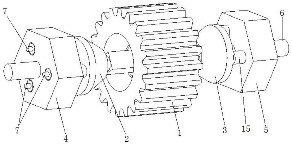
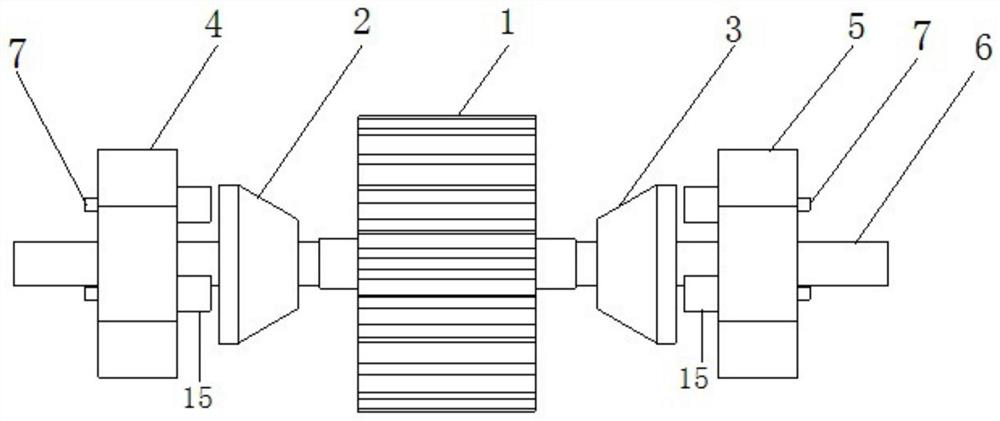
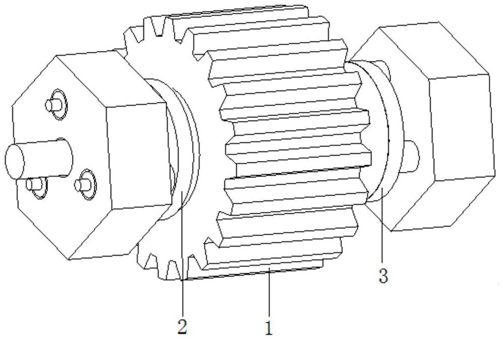
[0030] like Figure 1-12 As shown, this specific embodiment adopts the following technical scheme: the structure includes: synchronous pulley 1, left circular table friction sleeve 2, right circular table friction sleeve 3, left loading hydraulic body 4, right loading hydraulic body 5, transmission shaft 6, one-way Hydraulic valve head 7, loading hydraulic shaft 15, hydraulic piston 16, the central position of the synchronous pulley 1 is processed with a s...


PUM


Abstract

The invention discloses a hydraulic loading type internal friction overload protection synchronous pulley device, and belongs to the technical field of synchronous pulleys. The technical scheme that asynchronous pulley, a left circular truncated cone friction sleeve, a right circular truncated cone friction sleeve, a left loading hydraulic body and a right loading hydraulic body are arranged on atransmission shaft, loading hydraulic cylinder holes are formed in the left loading hydraulic body and the right loading hydraulic body, and hydraulic pistons are machined at one end of a loading hydraulic shaft and inserted into the loading hydraulic cylinder holes is adopted, and after the loading hydraulic cylinder holes are filled with high-pressure oil liquid with the pressure being P, the loading hydraulic shaft tightly abuts against the left circular truncated cone friction sleeve and the right circular truncated cone friction sleeve under the pressure of the high-pressure oil liquid;friction force between the left circular truncated cone friction sleeve and the synchronous pulley and friction force between the right circular truncated cone friction sleeve and the synchronous pulley are increased, transmission of the synchronous pulley is achieved through the friction force, when the transmission load torque on the transmission shaft is larger than the torque generated by thefriction force, the synchronous pulley and the transmission shaft slip, the overload protection effect is achieved, and the phenomena of tooth skipping, slipping and synchronous belt abrasion are prevented.

Description

technical field [0001] The invention relates to a hydraulic loading type internal friction overload protection synchronous pulley device, which belongs to the technical field of synchronous pulleys. Background technique [0002] Synchronous belt drive is meshing belt drive. Traditional large-span long-distance transmission mostly uses V-belt transmission or chain transmission, but the elastic sliding of V-belt transmission, noise and vibration in chain transmission greatly affect the performance of mechanical equipment, so in high-speed equipment, CNC machine tools, Synchronous belt drives are widely used in the robot industry, automobile industry, and textile industry. [0003] Timing belt drives transmit motion by the engagement of equally spaced transverse teeth on the inner surface of the belt and corresponding cogs on the pulley. Compared with the friction belt drive, there is no relative slip between the pulley and the drive belt of the synchronous belt drive, which ...

Claims


Application Information

Patent Timeline
Patent Type & Authority Applications(China)
IPC IPC(8): F16D43/21
CPCF16D43/218
Inventor 郭伟李涛涛
Owner 李涛涛
Why Eureka
Try Eureka