Energy storage CT energy management system and method

An energy management system and energy management technology, applied in the field of energy storage CT energy management system, can solve problems that affect the experience and serviceability of CT equipment, invalid radiation of patients, and stop rotation of racks, etc., so as to improve user friendliness and serviceability, avoid invalid radiation, and ensure forward-looking results

Pending Publication Date: 2020-11-06
上海大骋医疗科技有限公司
View PDF9 Cites 0 Cited by
  • Summary
  • Abstract
  • Description
  • Claims
  • Application Information

AI Technical Summary

Problems solved by technology

After the energy storage CT runs for a period of time, the stored energy decreases, resulting in insufficient power supply
In actual CT applications, there are mainly two situations that will affect the normal development of CT scanning services and affect the economic benefits and reliability of CT equipment applications.
[0004] In the first case, at the beginning of CT scanning, when the X-ray exposure components and CT moving components are started, several high-power components need to consume more power, and there will be an instantaneous power consumption peak, resulting in the CT energy storage components Unstable working conditions such as instantaneous low power and undervoltage occur, so that CT scanning has to be suspended or other equipment failures and damages are caused
[0005] In the second case, the CT scanning business can start normally, and after a period of time when the tube exposure and moving parts operate normally, the tube exposure may stop abnormally due to insufficient power, or the rack stops rotating, or the hospital bed stops running, or the board card The power supply is under-voltage reset, the scanning service cannot be completed normally, and the existing scanning data is invalid, requiring re-scanning, causing patients to suffer from invalid radiation, affecting the experience and serviceability of CT equipment

Method used


Image

  • Energy storage CT energy management system and method
  • Energy storage CT energy management system and method
  • Energy storage CT energy management system and method

Examples


Embodiment

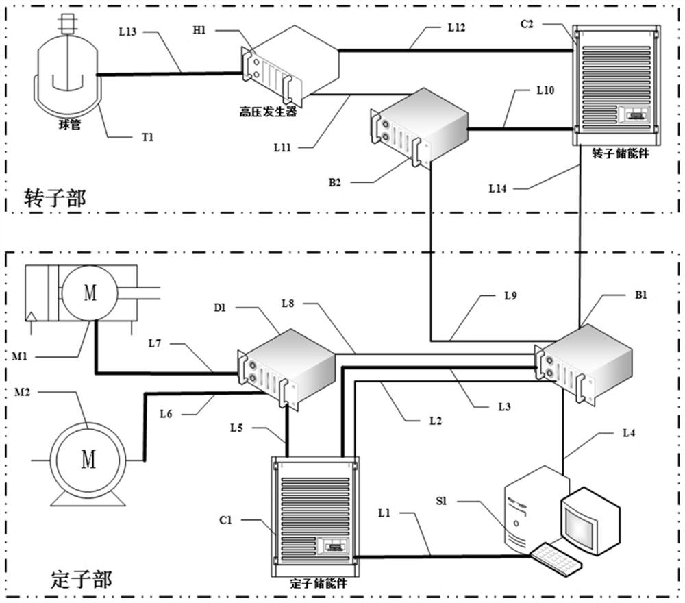
[0031] This embodiment provides an energy storage CT energy management system, such as figure 1 As shown, it includes stator energy storage part C1, scanning controller B1 and rotor energy storage part C2. Scanning controller B1 communicates with stator energy storage part C1, rotor energy storage part C2, exposure controller B2, and motion drive controller D1 respectively. and the console S1, the stator energy storage part C1 is powered and connected to the motion drive controller D1, the scanning controller B1 and the console S1, and the rotor energy storage part C2 is powered and connected to the exposure controller B2.

[0032] in particular:

[0033] The motion drive controller D1 is connected to the bed motion motor M1 and the frame motion motor M2, the exposure controller B2 is connected to the high voltage generator H1, and the high voltage generator H1 drives the bulb T1. Bed motion motor M1, frame motion motor M2, motion drive controller D1, stator energy storage pa...


PUM


Abstract

The present invention relates to an energy storage CT energy management system and method. The system includes a stator energy storage component, a scanning controller and a rotor energy storage component, wherein the scanning controller is respectively in communication connection with the stator energy storage component, the rotor energy storage component, an exposure controller, a motion drivingcontroller and a control console; the stator energy storage component is electrically connected with the motion driving controller, the scanning controller and the control console; and the rotor energy storage component is electrically connected with the exposure controller. Compared with the prior art, the energy storage CT energy management system guarantees the perspectiveness of electric quantity consumption, improves the service friendliness and serviceability of a scanning service, guarantees normal exposure and improves the reliability and safety of a CT device.

Description

technical field [0001] The invention relates to the field of energy storage CT, in particular to an energy storage CT energy management system and method. Background technique [0002] In the energy storage CT equipment, due to the limitation of the capacity of the energy storage component, the energy storage component can only hold a specific capacity of electric energy to provide energy for the normal operation of the energy storage CT. [0003] The X-ray exposure parts and CT moving parts in CT equipment are high-power parts, which consume a lot of electric energy when the tube is exposed, the rack is rotated, and the bed is moved. After the energy storage CT runs for a period of time, the stored energy decreases, resulting in insufficient power supply. In actual CT applications, there are mainly two situations that will affect the normal development of CT scanning services and affect the economic benefits and reliability of CT equipment applications. [0004] In the fi...

Claims


Application Information

Patent Timeline
Patent Type & Authority Applications(China)
IPC IPC(8): A61B6/03A61B6/00H02J7/00H04L12/40
CPCA61B6/032A61B6/035A61B6/54A61B6/542H02J7/0063H04L12/40A61B6/56A61B6/44H04L2012/40215
Inventor 陈牧徐军丁海波
Owner 上海大骋医疗科技有限公司
Why Eureka
Try Eureka