
Indicating light assembly installation structure of carbon dioxide laser machine

A technology of component installation and carbon dioxide, which is applied in the field of medical laser machines, can solve the problems of occupying the height space of the chassis, inconvenient installation and maintenance, and the size and space occupied by the indicator light components, so as to achieve the effect of convenient installation, convenient installation and maintenance, and lower design height

Pending Publication Date: 2020-11-06
SHANGHAI INST OF LASER TECH
View PDF0 Cites 0 Cited by
  • Summary
  • Abstract
  • Description
  • Claims
  • Application Information

AI Technical Summary

Problems solved by technology

[0005] 2) The indicator light component itself needs to occupy a certain size space;
[0007] 4) The laser tube is coaxial with the indicator light component. The length of the laser tube is fixed under the rated power, so the indicator light component will make the total height of the chassis higher, and the operation panel is installed on the top of the chassis, and the height of the chassis will be sensitively affected. Easy access to the operation panel
[0008] In addition to occupying the internal height space of the chassis, the installation of the indicator light component in the chassis will also bring inconvenience to installation and maintenance

Method used


Image

  • Indicating light assembly installation structure of carbon dioxide laser machine
  • Indicating light assembly installation structure of carbon dioxide laser machine
  • Indicating light assembly installation structure of carbon dioxide laser machine

Examples


Embodiment Construction

[0028] The present invention will be further described in detail below in conjunction with the accompanying drawings and specific embodiments. According to the following description, the purpose, technical solution and advantages of the present invention will be more clear. It should be noted that the described embodiments are preferred embodiments of the present invention, but not all embodiments.

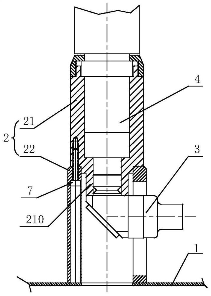
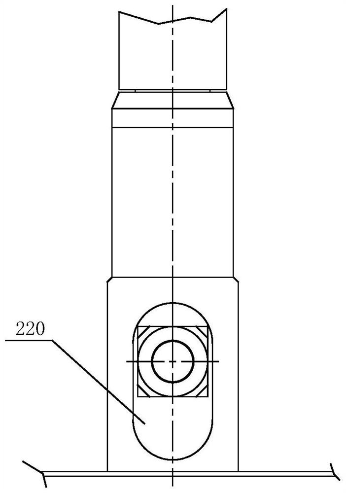
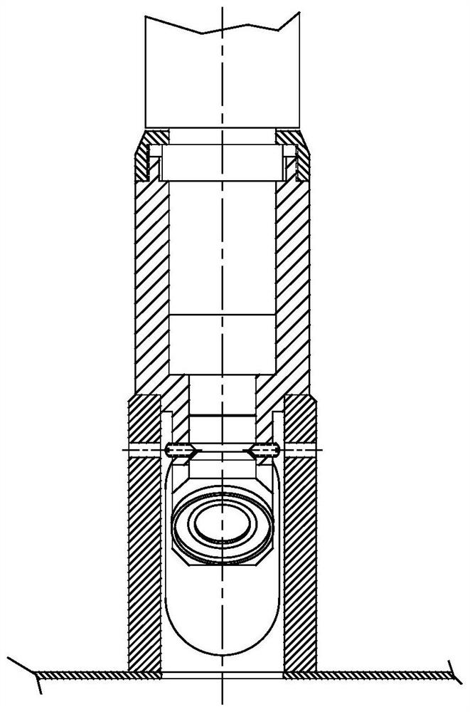
[0029] to combine Figure 1 to Figure 4 As shown, a carbon dioxide laser machine indicator light component installation structure, including the chassis 1, the light guide arm base assembly 2 installed on the top of the chassis 1 and the indicator light component 3, the indicator light component 3 is installed on the light guide arm base Middle section of component 2.

[0030] continue to refer figure 1 with figure 2 , the light guide arm base assembly 2 is cylindrical, and it includes the upper section 21 of the light guide arm base and the lower section 22 of the light gui...


PUM


Abstract

The invention relates to an indicating light assembly installation structure of a carbon dioxide laser machine. The indicating light assembly installation structure comprises a machine box, a light guide arm seat assembly and an indicating light assembly, wherein the light guide arm seat assembly and the indicating light assembly are installed at the top of the machine box, the indicating light assembly is installed in the middle section of the light guide arm seat assembly, the light guide arm seat assembly includes an upper section of a light guide arm seat and a lower section of the light guide arm seat, and the indicating light assembly is installed at the bottom of the upper section of the light guide arm seat. Further, a connecting part is arranged at the bottom of the upper sectionof the light guide arm seat, a long waist hole is formed in the side surface of the lower section of the light guide arm seat in a vertical direction, one end of the indicating light assembly is installed on the connecting part, and the other end of the indicating light assembly is located in a vertical hole. The indicating light assembly is installed outside the machine box, and installation, maintenance and replacement operations are more convenient; and because the indicating light assembly no longer occupies the internal space of the machine box, the design height of the machine box is effectively reduced, and the installation height of an operation panel is further reduced accordingly, so that medical staff can operate conveniently.

Description

technical field [0001] The invention relates to the technical field of medical laser machines, in particular to an installation structure of an indicating light component of a carbon dioxide laser machine. Background technique [0002] Carbon dioxide laser therapy instrument is a medical device mainly used for cutting, vaporizing, carbonizing, coagulating and irradiating human tissues to achieve therapeutic purposes. Widely used in ENT, dermatology, cosmetology, gynecology, neurosurgery and other surgical operations. It adopts a sealed-off CO2 laser to output invisible infrared laser. It is characterized by thin beam and high energy density. The laser is transmitted through the light-guiding joint arm, and it is suitable for various purposes with various cutter heads. [0003] refer to Figure 7 , in the prior art, the indicator light assembly 3 is usually installed at the bottom of the external light guide arm base 2' and inside the cabinet 1 as a necessary device for the ...

Claims


Application Information

Patent Timeline
IPC IPC(8): A61B18/20H01S3/03
CPCA61B18/20H01S3/03
Inventor 吴磊李佳君孙黛薇董岿然
Owner SHANGHAI INST OF LASER TECH
Learn More