Bit pressure controlled type downhole circulating pup joint and continuous pipe drilling plug dynamic flushing process

A control-type, weight-on-bit technology, applied in drill pipe, drilling equipment, flushing wellbore, etc., can solve the problem of increasing the degree of fatigue damage and deformation of the pipe string, the risk of sticking, restricting the application and promotion of coiled tubing drilling and grinding bridge plugs, Increase the operation time and cost to achieve the effect of improving the return speed and bridge plug drilling and grinding efficiency, promoting application and promotion, and improving efficiency

Pending Publication Date: 2020-11-06
CHONGQING UNIVERSITY OF SCIENCE AND TECHNOLOGY
View PDF0 Cites 1 Cited by
  • Summary
  • Abstract
  • Description
  • Claims
  • Application Information

AI Technical Summary

Problems solved by technology

Even so, in many cases, especially in highly deviated well sections, there will still be some abrasive debris that cannot be returned normally, resulting in the site being forced to lift and lower the pipe string many times, increasing the fatigue damage of the pipe string, deformation, and pipe sticking risk, or use strong magnetic tools to salvage, increasing operation time and cost
As a result, the application and promotion of coiled tubing drilling and grinding bridge plug technology is greatly restricted

Method used


Image

  • Bit pressure controlled type downhole circulating pup joint and continuous pipe drilling plug dynamic flushing process
  • Bit pressure controlled type downhole circulating pup joint and continuous pipe drilling plug dynamic flushing process
  • Bit pressure controlled type downhole circulating pup joint and continuous pipe drilling plug dynamic flushing process

Examples


Embodiment Construction

[0038] The present invention will be further described below in conjunction with embodiment and accompanying drawing.

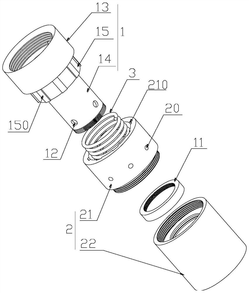
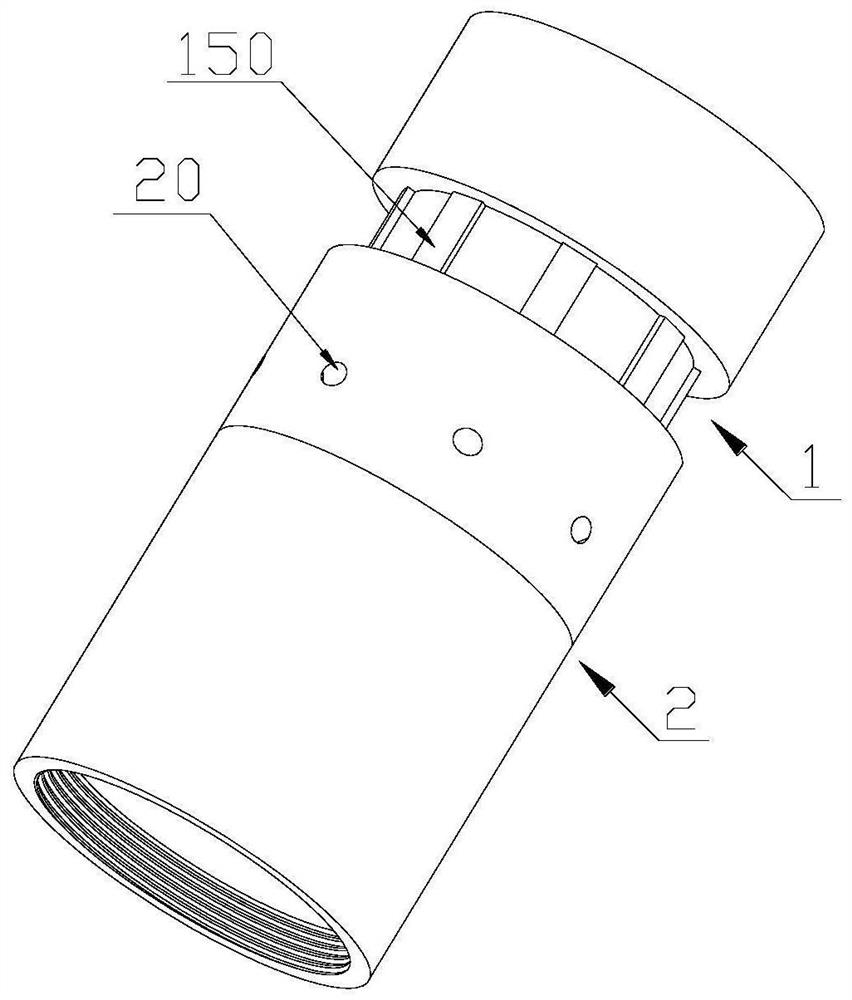
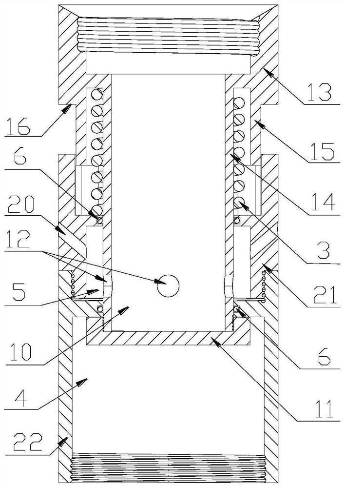
[0039] refer to Figure 1 to Figure 10 The pressure-on-bit controlled downhole circulation short connection and coiled tubing plug dynamic flushing process are shown, wherein the pressure-on-bit control downhole circulation short connection mainly includes an upper joint body 1 and a lower joint body 2, both of which are generally hollow tubular structures, and the upper joint body The body 1 and the lower joint body 2 are relatively movably connected, that is, the two can slide relative to each other along the axis, and an elastic element 3 is arranged between the two. The elastic element 3 is mainly used to assist the two to return to their original positions when they are not under pressure. , the upper end of the upper joint body 1 and the lower end of the lower joint body 2 both have threaded buckles for connecting with corresponding drilling tools.

[00...


PUM


Abstract

The invention discloses a bit pressure controlled type downhole circulating pup joint and a continuous pipe drilling plug dynamic flushing process. The circulating pup joint comprises an upper joint body and a lower joint body which are in sliding fit through an elastic element. Flow passing holes are formed in the lower end of the side wall of the upper joint body. A front spraying passageway anda side spraying passageway are arranged between the lower joint body and the upper joint body, and the lower joint body can slide in the axial direction of the upper joint body, so that one of the flow passing holes communicates with the front spraying passageway or the side spraying passageway. Side spraying holes are formed in the side wall of the lower joint body, and the side spraying holes are arranged obliquely upwards. The circulating pup joint is mainly adopted in a drilling and grinding process, and drilling and grinding operation is carried out after reasonable bit pressure parameters are determined; and the speed is increased through an optimized lateral jet flow structure, delivery capacity and tubular columns, dynamic flushing and upward grinding returning are carried out, and finally drilling and grinding circulation is repeated until all work is completed. The pup joint is ingenious in overall structure, long in service life and convenient to operate; and according to the process, the grinding flushing effect can be improved, the continuous pipe drilling plug benefits can be increased, and popularization and application of the technology can be promoted.

Description

technical field [0001] The invention relates to the technical field of oil and gas well development, in particular to a pressure-on-bit control type downhole circulation short connection and continuous pipe drilling plug dynamic flushing technology. Background technique [0002] In recent years, with the large-scale development of shale gas and tight low-permeability oil and gas reservoirs at home and abroad, staged multi-cluster fracturing with drillable bridge plugs in horizontal wells has been widely used. This technology forms a complex fracture network system through clustered perforation and layered fracturing, improves reservoir seepage rate, and has obvious effects on stimulation of shale gas and tight low-permeability oil and gas reservoirs. After completing the fracturing operation in all intervals, using coiled tubing to carry milling tools to drill and grind the residual bridge plugs in the wellbore can not only improve the construction efficiency and save produc...

Claims


Application Information

Patent Timeline
Patent Type & Authority Applications(China)
IPC IPC(8): E21B21/00E21B17/02E21B29/00
CPCE21B17/021E21B21/00E21B29/00
Inventor 郭晓乐张迪盛岳凡钦刘继林
Owner CHONGQING UNIVERSITY OF SCIENCE AND TECHNOLOGY
Why Eureka
Try Eureka